")
Throughout a product's lifecycle, designs are revisited by various experts, crossing multiple departments or even partnering companies. Swiftly detecting changes and discrepancies between different CAD models and mesh data from simulations is vital. CADfix provides three innovative tools for CAD, CAE, simulation, and advanced manufacturing. These tools guide users in effortlessly identifying variances between CAD models and meshes.
Mesh to CAD Comparison
The first comparison tool, Mesh to CAD, pits a CAD model against its associated CAE mesh. This is a crucial step to ensure that the mesh faithfully reflects the CAD geometry for simulations and modeling. It handles surface and volume meshes of various kinds. For volumetric meshes, the shell of the solid elements is extracted for comparison. This tool reveals the most significant discrepancy between the mesh and the CAD, highlighting the concerned areas. If inconsistencies appear, CADfix identifies and visually flags them. Moreover, this tool's performance has been optimized to manage substantial meshes.
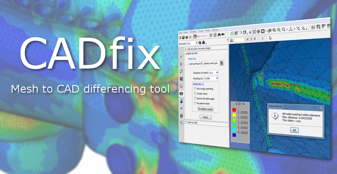
Illustration of Mesh-CAD correspondence
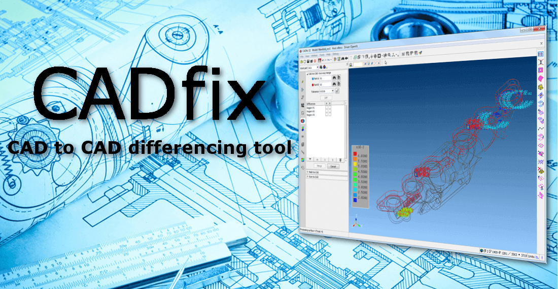
CAD/CAD 3D Differencing
The second tool offers CAD/CAD 3D differencing capabilities. It allows for quick detection of modifications between two CAD models, typically during design revisions. A hybrid model can thus be created, merging selected elements from each version. This comparison and assembly method allows for integrating simplified features from a previous CADfix session while adding new features from the latest version.
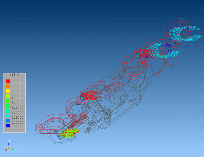
View of the CAD/CAD 3D Differencing tool
Scan to CAD Comparison
Lastly, a tool dedicated to comparing a 3D scan with the original CAD model is provided. This tool reveals the discrepancies between the CAD design and the scanned, manufactured product. Scanned data in STL and PLY formats can be imported. It highlights areas showing the greatest differences, providing information about manufacturing accuracy.
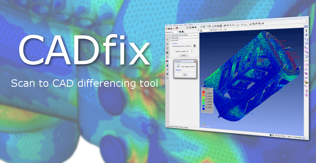
Demonstration of Scan-CAD comparison
In conclusion, CADfix establishes itself as an indispensable partner for any professional aiming to master the comparison between CAD models and meshes from numerical simulations. Its range of tools ensures perfect synergy between design and simulation, guaranteeing reliable results and optimized processes.