")
CAD systems
Based on our over 25 years experience, CAD Interop recommends below the most relevant CAD formats to convert your data between major CAD systems. To date, the most common exchange format is the STEP format, the most complete and available for the majority of CAD software. But, when possible, it is preferable to use the geometry kernel of the software (such as Parasolid for NX, SolidWorks or Solid Edge) which will allow to read the geometry without translation. If you want to provide read-only access to your CAD data for users who do not have a viewer or other CAD software, we recommend using the 3D PDF format in its faceted (lighter) version.
| |||||||||||||||||||||||||||||||||||||||||||||||||
(*) recommended neutral file format for 3D geometry interoperability
(1) Only major neutral file formats are listed. Some CAD systems may have some limitations with specific format.
CAD Interop distributes several solutions to view, translate or validate CAD files. Find below the list of our products compatible with major CAD formats.
Table of Contents
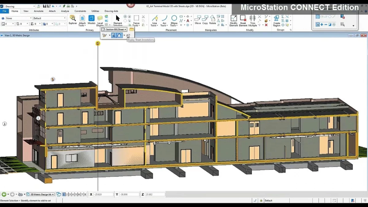
Technical data interoperability represents a major challenge for companies using multiple CAD systems, particularly in engineering, architecture, and construction sectors. MicroStation, developed by Bentley Systems, offers interoperability capabilities enabling seamless data exchange with other CAD platforms. This guide examines MicroStation's interoperability capabilities, its data exchange mechanisms, and complementary solutions to optimize multi-CAD workflows.
In an industrial environment where multi-disciplinary collaboration has become the norm, mastering MicroStation interoperability represents a strategic advantage for technical teams. Challenges related to CAD data exchange directly impact engineering project productivity and the quality of final deliverables.
MicroStation Interoperability Ecosystem
MicroStation distinguishes itself through its flexible approach to CAD interoperability, allowing direct interaction with numerous formats without systematically requiring intermediate conversions. This characteristic facilitates MicroStation integration in heterogeneous environments where multiple CAD systems coexist. The platform offers the possibility to reference, import, visualize, and modify files from various sources while preserving the integrity of technical data.
MicroStation's open architecture promotes fluid data exchange and adapts to the requirements of different phases in engineering project lifecycles. From initial design to manufacturing and long-term archiving, the MicroStation ecosystem enables essential digital continuity for complex projects.
Key Components of the Interoperability Ecosystem
- Integrated multi-format referencing engine
- Bidirectional translation capabilities with metadata preservation
- Support for international exchange standards
- Automatic geometric healing mechanisms
- Integration with PLM and document management systems
Supported Formats and Data Exchange Mechanisms
MicroStation supports a wide range of native formats and exchange standards, facilitating interoperability with various CAD platforms. This flexibility allows companies to maintain efficient workflows even in complex multi-CAD environments.
Native and Proprietary Formats
- DGN - MicroStation's native format with full feature support
- DGN V7/V8 - Compatibility with previous MicroStation versions
- DWG/DXF - Native support for AutoCAD formats via RealDWG 2016
- SKP - Import of SketchUp models
- 3MX - Support for Acute3D models for reality capture
Neutral Exchange Standards
- STEP (AP203, AP214, AP242) - ISO standard for product data exchange
- IFC - Building Information Modeling (BIM) format
- JT - Lightweight format for 3D data visualization and exchange
- 3D PDF - Interactive technical documentation format
- IGES - Historical standard for CAD data exchange
Data Exchange Mechanisms
MicroStation offers four main mechanisms for interacting with external data:
- Referencing - Attaching external files without modifying the original
- Importing - Converting external data to native DGN format
- Exporting - Converting DGN data to other formats
- Direct editing - Modifying certain external formats without prior conversion
MicroStation's Interoperability Advantages
MicroStation's interoperability approach offers several strategic advantages for companies managing complex projects involving multiple CAD formats. These strengths help optimize engineering workflows and reduce risks associated with data conversion.
Key Advantages
- Data translation fidelity - Preservation of geometric characteristics, annotations, and PMI during conversions
- Conversion-free workflows - Ability to work directly with referenced files without mandatory conversion
- Stability with large datasets - Efficient management of complex and voluminous models
- Preserved metadata - Retention of critical technical information during exchanges
- Complete Model-Based Definition (MBD) support - Maintenance of 3D dimensions and tolerances during exchanges
When benchmarking against other CAD solutions, MicroStation demonstrates a more flexible approach to interoperability. Its ability to handle multi-format references without mandatory conversion helps maintain source data integrity while facilitating collaboration between teams using different CAD systems.
Advanced Interoperability Features
Beyond standard data exchange capabilities, MicroStation offers advanced features that optimize interoperability in complex scenarios. These tools allow engineers to effectively manage multi-CAD projects while preserving the richness of technical data.
Advanced Translation and Exchange Features
- Complete support for complex DWG objects - Multileaders, annotation objects, sublayers, and tables
- Integration with Oracle Spatial databases - Connectivity with Oracle 12c for geospatial data management
- Incorporation of high-resolution 3D models - Support for models created through photogrammetry
- Georeferenced export - Ability to export to Google Earth with correct altitude preservation
- 3D printing support - Export to 3D printing formats with texture preservation
How to Ensure Data Consistency During Multi-CAD Exchanges?
MicroStation integrates several validation mechanisms that ensure data quality during exchanges between different CAD systems:
- Automatic detection and repair of geometric errors
- Verification of compliance with exchange standards
- Conversion audit reports with identification of critical elements
- Preservation of assembly hierarchical structures
- Maintenance of component trees and their relationships
CAD Interop Solutions for MicroStation Format
CAD Interop distributes specialized solutions that complement and extend MicroStation's native interoperability capabilities. These tools provide advanced visualization, analysis, and data preparation functionalities that address specific needs of MicroStation users.
3DViewStation: Advanced Visualization and Analysis of MicroStation Models
3DViewStation is a powerful visualization and analysis solution offering complete support for the MicroStation DGN format. It allows companies to extend accessibility of MicroStation data throughout the organization without requiring full licenses for each user.
Key Features of 3DViewStation for MicroStation
- High-performance visualization of complex DGN models with reduced system footprint
- Advanced technical analysis - Measurement, sectioning, model comparison
- Exploded view generation for technical documentation
- Bidirectional conversion between MicroStation and numerous formats (STEP, JT, 3D PDF)
- Creation of technical animations from MicroStation models
- Extraction of PMI (Product Manufacturing Information) and 3D annotations
3DViewStation constitutes an ideal solution for extended teams requiring access to MicroStation data without modifying original files. Its ability to convert to MicroStation format also allows integration of data from other CAD systems into the MicroStation environment.
CADfix: Repair and Simplification of MicroStation Data
CADfix is a specialized solution for validation, repair, and optimization of CAD models. For MicroStation users, CADfix offers advanced data preparation capabilities that go beyond the native functionalities of the software.
CADfix Capabilities for MicroStation Data
- Advanced geometric healing - Detection and correction of complex errors in B-rep models
- Intelligent simplification of voluminous assemblies for visualization or analysis
- Model validation according to exchange standard requirements or internal processes
- Manufacturing preparation - Adaptation of models for CAM processes or 3D printing
- High-precision conversion between MicroStation and other CAD formats
- Controlled defeaturing - Selective removal of non-essential features
CADfix effectively resolves data quality issues that can occur during exchanges between MicroStation and other CAD systems. Its ability to maintain geometric integrity while optimizing models makes it a valuable tool for heterogeneous engineering environments.
Why Use Specialized Solutions with MicroStation?
Although MicroStation offers native interoperability capabilities, specialized solutions like 3DViewStation and CADfix provide several complementary advantages:
- More thorough processing of complex data quality issues
- Extension of visualization and analysis capabilities without full licenses
- Automation of data preparation workflows for specific processes
- Specialized tools adapted to particular business needs
- Facilitated integration with other enterprise systems (PLM, ERP)
Strategies and Best Practices for Optimal Interoperability
Optimizing interoperability in an environment involving MicroStation requires adopting appropriate strategies and methodologies. These best practices help minimize conversion problems and maximize the quality of data exchanges.
Fundamental Principles for MicroStation Data Exchange
- Avoid unnecessary conversions - Prioritize direct referencing when possible
- Establish consistent naming conventions and organization across platforms
- Document translation processes and their parameters to ensure reproducibility
- Systematically validate converted data before production use
- Maintain a library of standard components in the various required formats
Optimal Configuration for Interoperability
MicroStation parameter configuration directly influences the quality of data exchanges. Here are the essential aspects to consider:
- Appropriate definition of units and tolerances for each project
- Seed file parameter configuration adapted to planned exchanges
- Establishment of specific templates for multi-CAD projects
- Setting import/export options according to project requirements
- Creation of documented workflows for recurring translation processes
How to Effectively Structure a Project Involving Multiple CAD Formats?
The structure of a multi-CAD project with MicroStation should follow these principles:
- Organize data by discipline rather than by format
- Maintain a clear file tree with limited hierarchical levels
- Use worksets to isolate data from different sources
- Establish a central directory for multi-format external references
- Implement a versioning system adapted to multi-CAD exchanges
Conclusion
CAD interoperability represents a strategic issue for companies using MicroStation in multi-software environments. MicroStation's native capabilities, combined with specialized solutions like 3DViewStation and CADfix distributed by CAD Interop, offer a complete ecosystem to effectively address technical data exchange challenges.
By adopting the best practices presented in this guide, engineering teams can optimize their workflows involving MicroStation, reduce risks associated with data conversions, and improve collaboration between different disciplines. Interoperability no longer constitutes an obstacle but becomes an efficiency lever in managing the lifecycle of engineering products and projects.
To deepen your mastery of MicroStation interoperability or explore solutions adapted to your specific needs, don't hesitate to contact CAD Interop experts who can guide you toward the most relevant tools and methodologies for your technical context.
In today's industrial landscape, CAD data interoperability is a major challenge for engineering, energy, and process industries. AVEVA PDMS and AVEVA E3D Design software are essential benchmarks in this field, offering advanced features for 3D modeling of complex facilities. This in-depth analysis explores their technical characteristics, recent developments, and integration into modern workflows, while highlighting the interoperability solutions offered by CAD Interop to optimize the exchange and management of design data.
Technological Context and Industrial Challenges
Evolving Plant Design Needs
Process industries (petrochemicals, energy, pharmaceuticals) and naval sectors are facing increasingly complex projects, requiring tools capable of managing multi-site 3D models with thousands of components. Challenges include coordination between disciplines (piping, structural, electrical), revision management, and collaboration with external partners using disparate software.
AVEVA PDMS, developed in the 1980s, marked a revolution thanks to its parametric approach and centralized database. However, the emergence of new methodologies such as BIM (Building Information Modeling) and increased simulation requirements have led to the development of AVEVA E3D Design, a direct successor incorporating expanded capabilities.
Limitations of Older Generations of Software
Although PDMS remains widely deployed, its monolithic architecture presents constraints in modern contexts:
- Difficulty integrating with PLM/ERP systems
- Limitations in managing large models (>500,000 elements)
- Time-consuming file conversion processes for external collaborations
- User interface poorly suited to agile workflows.
These limitations explain the gradual migration to E3D Design, whose performance has been optimized for megaprojects, with productivity gains estimated at between 30% and 50% off the preliminary design phases.
PDMS/E3D Design Comparative Analysis: Technical Architecture and Key Features
AVEVA PDMS: Historical Foundations
- Parametric Modeling: Library of standard components (ASME, DIN, ISO)
- Clash Management: Automatic detection of cross-disciplinary interference
- Multi-User Workflow: Granular locking of elements in editing
- Documentation Generation: Automated assembly drawings, isometrics, and bills of materials.
The native .rvm format integrates a hierarchical representation of data, storing both geometry (NURBS and meshes) and technical metadata (materials, operating pressures):
- .rvm: AVEVA Plant Design Management System Template
- .rvs: AVEVA Plant Design Management System Project
- .pdms: AVEVA PDMS Document
The RVM file format can be saved in both binary and ASCII formats. The RVM file supports entities such as:
- Geometry
- Attributes stored on groups
- Textures (via RVS file)
- Cameras and camera tracks (via RVS file)
- Clip planes (via RVS file)
- Panels (via RVS file)
- Tags (via RVS file)
- Labels (via RVS file)
- Translucency (via RVS file)
- PDMS origin points
AVEVA E3D Design: The Technological Evolution
- Associative Modeling: Dynamic Data Linking P&ID
- Cloud Integration: Real-time collaboration via AVEVA Connect
- Advanced Clash Management: AI-based detection algorithms
- Extensive Interoperability: Native support for IFC 4.3 and STEP AP242 formats.
The .e3d data structure introduces a built-in versioning system and LZ77 compression mechanisms for files larger than 10 GB. Comparative tests show a 40% reduction in loading time for complex models compared to PDMS.
Exchange Capacity Comparison Table
| Criterion | PDMS (.rvm) | E3D Design (.e3d) |
|---|---|---|
| Export formats | 15+ (STEP, IGES) | 25+ (JT, 3D PDF) |
| Geometric precision | ±0.1 mm | ±0.01 mm |
| Technical metadata | Proprietary | ISO Standardized |
| Data Compression | No | LZ77 (5:1 ratio) |
| LOD Support | Level 2 | Levels 1-4 |
This table summarizes E3D Design's major advances in interoperability, crucial for multi-software workflows.
Strategic Migration to E3D Design
Planning and Best Practices
Transitioning from PDMS requires a structured approach :
- Existing Data Audit: Analysis of .rvm/.pdms files to identify potential incompatibilities
- Progressive Conversion: Use of AVEVA Migration Toolkit with batch validation
- Team Training: e-Learning modules tailored to specific business lines (engineering, purchasing, construction)
- System Integration: Custom connectors for SAP/Teamcenter ERPs.
Case studies at TechnipFMC reveal a 70% reduction in conversion errors thanks to E3D Design's backward compatibility algorithms.
Legacy Format Management
CAD Interop offers specialized solutions to maintain access to historical PDMS data :
- Visualization: .rvm/.pdms compatible software with measurements and annotations
- Batch Conversion: Transformation to .e3d with metadata preservation
- Geometric Validation: Topological error detection tools.
These tools enable a seamless transition of ongoing projects while securing existing digital assets.
Integration into modern CAD ecosystems
Interoperability Connectors
AVEVA E3D Design offers broad compatibility with numerous file formats, facilitating data exchange and collaboration between various software tools used in the engineering, procurement, and construction (EPC) industries. Here is a detailed list of supported formats:
Common import and export formats
| Format | Extension | Import | Export |
|---|---|---|---|
| AutoCAD | .dwg, .dxf | ✓ | ✓ |
| MicroStation | .dgn | ✓ | ✓ |
| Navisworks | .nwd, .nwf | ✓ | ✓ |
| PDMS | .rvm, .cdb | ✓ | ✓ |
| SolidWorks | .sldprt, .sldasm | ✓ | ✓ |
| STEP | .stp, .step, AP203, AP214, AP242 | ✓ | ✓ |
| IGES | .igs, .iges | ✓ | ✓ |
| STL | .stl | ✓ | ✓ |
| VRML | .wrl | ✓ | ✓ |
| CATIA V4 | .model, .exp | ✓ | |
| CATIA V5/V6 | .CATPart, .CATProduct | ✓ | |
| Creo (Pro/E) | .prt, .asm | ✓ | |
| Inventor | .ipt, .iam | ✓ |
Additional Specific Formats
- Parasolid: (.x_t, .x_b) - Full import and export
- ACIS: (.sat, .sab) - Full import and export
- Images: (.bmp, .jpg, .tif) - Import only
These formats enable extensive interoperability with the main CAD software used in industry.
Interoperability Methods with AVEVA
Optimizing Data Exchange
- Using Formats neutral: Prefer formats like STEP to maximize compatibility between different CAD tools while preserving general attributesmetric and technical.
- Simplify Complex Models: Use tools like CADfix PPS to reduce file size before importing into AVEVA E3D. This improves performance and reduces processing times for large models.
Attribute and Metadata Management
- When exchanging with Tekla Structures or other BIM software, favor exporting to IFC format to ensure that essential attributes (materials, dimensions) are preserved.
- For legacy PDMS files (.rvm), ensure that entities such as textures or tags are correctly transferred via the associated RVS file.
Multi-Software Collaboration
- Directly integrate data from other disciplines using AVEVA Unified Engineering connectors. This allows for automatic updates between electrical schematics and the 3D model.
- Use compatible visualization solutions like 3DViewStation to quickly validate models without requiring prior conversion.
Post-Conversion Quality Control
After each conversion or import:
- Check for interferences and clashes using E3D Design's built-in tools.
- Compare models before and after conversion with specialized software to detect any loss of information or geometric errors.
These tips ensure a smooth transition between software while minimizing the risk of errors in your industrial projects.
Future Outlook and Innovations
AI and Digital Twin Integration
The latest versions of E3D Design integrate artificial intelligence modules for:
- Automatic Route Generation: Optimization of piping networks
- Predictive Interference Detection: Algorithms based on project history
- Documentation Synthesis: Automatic generation of technical reports.
Integration with AVEVA Process Simulation creates a complete digital twin, enabling multiphysics simulations directly on the 3D model.
Extended Reality (XR) Developments
CAD Interop develops immersive visualization solutions:
- Virtual Reality: Collaborative Project Reviews in a CAVE Environment
- Cloud Streaming: Lightweight access to models via a web browser.
These technologies reduce validation times by 40% while improving the early detection of design issues.
Conclusion
Migrating to AVEVA E3D Design represents a strategic opportunity for companies looking to optimize their 3D factory design processes. Combined with CAD Interop's interoperability solutions, this software enables seamless integration into modern CAD ecosystems while preserving access to historical data. The gains in productivity, deliverable quality, and error reduction fully justify the investment, particularly in the current context of accelerating complex industrial projects.
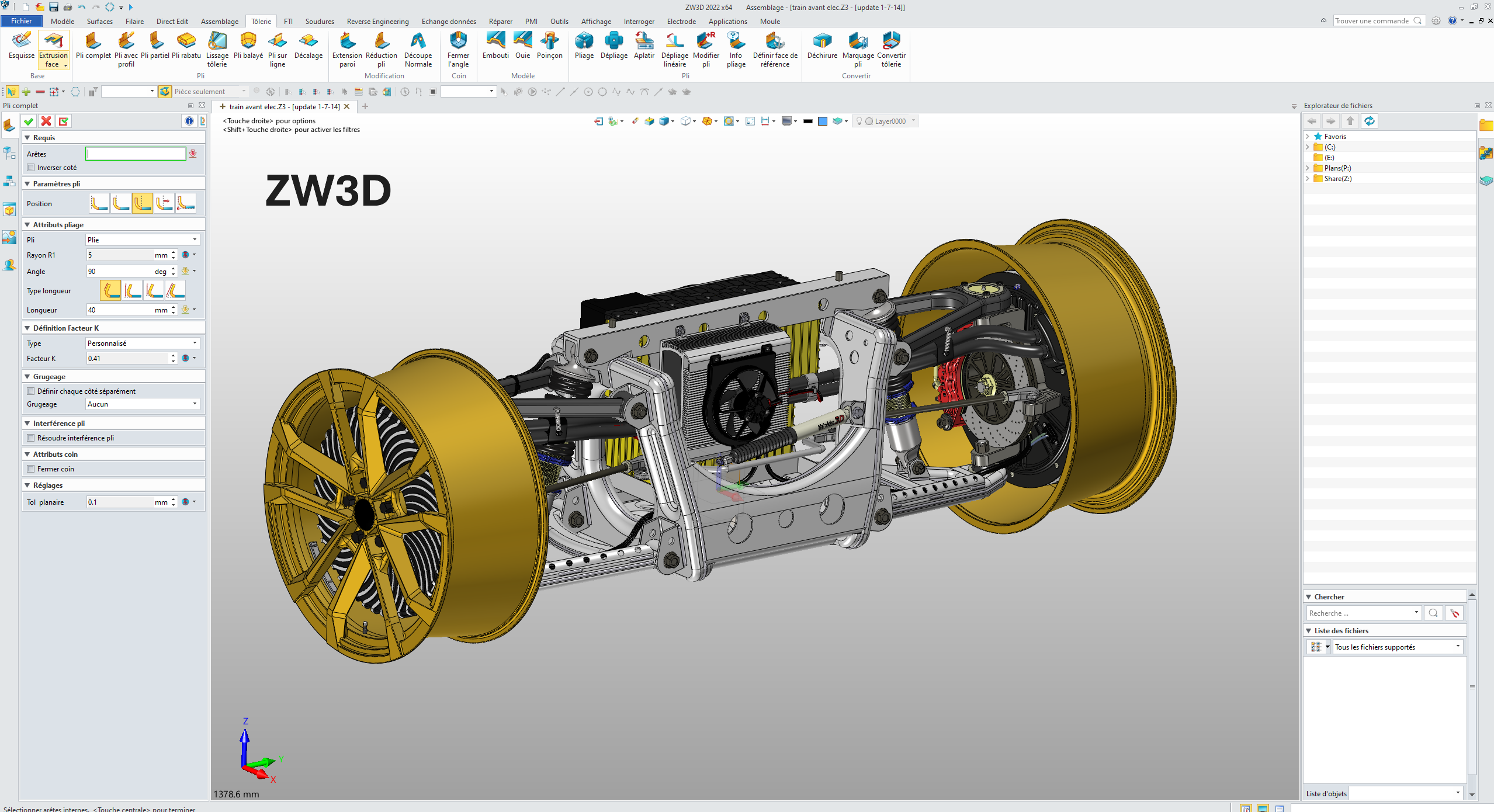
Table of Contents
- Introduction to ZW3D and Interoperability
- History and Evolution of ZW3D
- The Overdrive Geometric Engine
- Formats and Standards Supported by ZW3D
- Interoperability with Other CAD Systems
- SimLab: Immersive Experience Solution for ZW3D
- Best Practices for Exchanging ZW3D Models
- Conclusion
Introduction to ZW3D and Interoperability
Computer-aided design data interoperability represents a major challenge for industrial companies working with multiple CAD systems. ZW3D positions itself as a high-performance solution to these technical data exchange issues, offering a complete response to CAD interoperability needs.
ZW3D is an advanced 3D CAD/CAM software developed by ZWSOFT, designed to offer an all-in-one solution for product design, manufacturing, and simulation. What particularly distinguishes ZW3D is its exceptional native interoperability capability with most CAD systems on the market.
The main advantages in terms of interoperability are:
- Direct opening of native files from many competing CAD systems
- Wide range of import and export formats
- Data translation without loss of geometric quality
- No need for third-party converters or add-ons in most cases
- Easy sharing and exchange with partners and suppliers
History and Evolution of ZW3D
Innovative Origins
Appearing in the CAD landscape in 1986 under the original name ModelMATE, ZW3D represented one of the very first commercial solid modelers operating on PC. Developed by Mark Vorwaller, this software already foreshadowed the future importance of technical data interoperability.
The year 1999 marks a decisive turning point with the introduction of Solid-Surface hybrid modeling technology, making ZW3D the first hybrid modeler in the industry. This major innovation removed the traditional boundaries between solid and surface modeling, allowing solid functionalities to be applied directly to surfaces.
Recognition and Continuous Development
Following a strategic alliance with SNK (Japanese machine tool company), ZW3D transformed into one of the first complete integrated design-manufacturing solutions. This evolution earned it the prestigious "Gold Winner & Product of the Year" award from NASA Tech Brief in 2002.
In 2010, ZWSOFT acquired the technologies and R&D team of VX Corporation in the United States, significantly enriching its multi-CAD interoperability and data exchange capabilities. Since then, ZW3D's continuous development has focused on improving data exchange performance with the main players in the CAD market.
The Overdrive Geometric Engine
A Powerful Proprietary Geometric Kernel
The core of ZW3D's CAD interoperability lies in its Overdrive geometric engine, a 3D modeling technology with completely independent intellectual property. Developed over more than 10 years, this kernel ensures the consistency of 3D models in their geometric shapes and spatial relationships thanks to sophisticated algorithms.
Overdrive offers a unique combination of features focused on interoperability:
- Smooth import and export of models from/to other systems
- Automated detection and repair of geometric defects
- Hybrid solid-surface modeling in a unified environment
- Coexistence of parametric and direct modeling
- Direct boolean operations between solids and surfaces
Proven Industrial Applications
The Overdrive engine has proven its effectiveness in various industrial sectors such as automotive, mechanical engineering, and electronics. It also serves as a technological foundation for other ZWSOFT solutions such as ZWSim-EM, ZWSim Structural, and ZWMeshWork.
What particularly distinguishes Overdrive in the field of interoperability is its ability to maintain model integrity during format conversions, significantly reducing geometric problems that typically occur during exchanges between different CAD systems.
Formats and Standards Supported by ZW3D
Broad Compatibility for Maximum Interoperability
ZW3D excels in supporting a wide range of CAD formats, enabling smooth collaboration with partners and suppliers using other systems. This section details the import and export formats supported by ZW3D.
The table below presents the main formats compatible with ZW3D, classified by categories:
| Category | Format | Extensions |
|---|---|---|
| Native Formats | Catia V4 | .model, .exp, .session |
| Catia V5/V6 | .CATPart, .CATProduct, .CATDrawing, .CGR, .3DXML | |
| NX(UG) | .prt | |
| Creo(Pro/E) | .prt, .prt*, .asm, .asm.* | |
| SolidWorks | .sldprt, .sldasm | |
| SolidWorks_2D | .slddrw | |
| SolidEdge | .par, .asm, .psm | |
| Inventor | .ipt, .iam | |
| Neutral Standards | ACIS | .sat, .sab, .asat, .asab |
| STEP | .stp, .step, .stpz | |
| IGES | .ige, .iges | |
| Parasolid | .x_t, .x_b, .xmt_txt, .xmt_bin | |
| JT | .jt | |
| VDA | .vda | |
| 2D Format | DWG | .dwg |
| DXF | .dxf | |
| Mesh and Visualization | STL | .stl |
| OBJ | .obj | |
| 3DXML | .3dxml | |
| XCGM | .xcgm | |
| Others | Image File | .bmp, .gif, .jpg, .jpeg, .tif, .tiff |
| Neutral File | .z3n, .v3n | |
| PartSolutions | .ps2, .ps3 |
This extensive compatibility enables efficient 3D data conversion and facilitates long-term archiving of technical models in standard formats such as STEP or JT.
Interoperability with Other CAD Systems
Versatile Alternative to Established Systems
ZW3D positions itself as an excellent alternative to established CAD solutions such as SolidWorks, Inventor, or Rhino, with similar functionalities but a differentiated approach to interoperability. Its ability to directly open and modify files from other CAD systems without third-party converters represents a major asset for companies working in multi-CAD environments.
ZW3D's interoperability capabilities revolve around three main axes:
- Hybrid volume-surface modeling: Enables precise design simultaneously integrating volumetric and surface approaches, facilitating exchanges with different systems
- Native multi-CAD compatibility: Works directly with SolidWorks, CATIA, NX and other files without intermediate conversions
- CAD-CAM integration: Smooth transfer of design data to manufacturing modules
Interoperability Use Cases
In a typical industrial environment, ZW3D can serve as a central hub for data translation between different CAD systems. For example, a company receiving CATIA models from its clients can open them in ZW3D, modify them if necessary, and then export them to SolidWorks for its manufacturing partners.
This technical data exchange flexibility allows companies to maintain their preferred CAD system while effectively collaborating with partners using other platforms, thus eliminating traditional interoperability barriers.
SimLab: Immersive Experience Solution for ZW3D
Advanced Interactive Visualization
SimLab Composer, distributed by CAD Interop, represents a powerful solution for creating immersive experiences from ZW3D models. This free plugin establishes an intermediate layer between ZW3D and the SimLab Composer application, creating an active link that keeps data synchronized between the two environments.
This integration eliminates the need for repetitive exports and imports: each modification of the model in ZW3D is automatically reflected in SimLab Composer, while preserving the changes made in the visualization environment.
Key Features for Technical Collaboration
SimLab Composer enriches the ZW3D ecosystem with advanced visualization and sharing capabilities:
- Creation of interactive VR experiences in minutes
- Realistic and fast rendering with multiple output formats (images, videos, animations, 360° views)
- Generation of 3D PDF documents integrating interactive 3D views
- Application of materials and texture baking for realistic rendering
- Mechanism simulation from ZW3D models
These features facilitate technical communication between teams and with clients, transforming complex CAD models into understandable visualizations for all project stakeholders, even those without CAD systems.
Best Practices for Exchanging ZW3D Models
Optimizing Interoperability Flows
To maximize the efficiency of data exchanges with ZW3D, certain recommended practices help avoid common data translation problems and ensure model integrity:
- Prefer standard formats such as STEP or JT for exchanges with external partners
- Use the native ZW3D format (.z3) to preserve construction history between collaborators
- Leverage hybrid modeling to facilitate exchanges with systems centered on surfaces or solids
- Systematically verify geometric quality after import/export with integrated healing tools
How to Effectively Manage Multi-CAD Conversions?
For companies working in a multi-CAD environment, adopting a structured data exchange process with ZW3D can significantly improve productivity:
- Define clear exchange standards for each partner CAD system
- Document optimal import/export parameters for each format
- Implement systematic geometric validation after conversion
- Use SimLab to visually validate converted models
- Maintain a library of reference models to test conversions
These practices help establish a robust interoperability workflow around ZW3D, reducing conversion errors and accelerating product development cycles.
Conclusion
CAD data interoperability represents a strategic issue for modern industrial companies, and ZW3D offers a high-performance solution to this problem thanks to its extensive technical data exchange capabilities. With its Overdrive geometric engine, compatibility with a wide range of CAD formats, and hybrid modeling approach, ZW3D enables smooth integration into multi-CAD ecosystems.
The main assets of ZW3D for interoperability can be summarized as follows:
- Native support for numerous standard and proprietary formats
- Advanced modeling capabilities facilitating exchanges between systems
- Integration with SimLab for immersive visualization and sharing
- Flexibility of use as a central data exchange platform
For companies looking to optimize their technical data exchange processes, ZW3D represents a complete solution that can either serve as a main CAD system or as an interoperability hub between different platforms. Its ability to maintain model integrity during conversions makes it a valuable tool for any collaborative multi-CAD design environment.
- History and Evolution of Revit
- Revit's Geometric Engine and Its Specificities
- Exchange Formats Supported by Revit
- IFC4 Format Support: A Decisive Step Towards Complete Interoperability
- CAD Interop Solutions for Revit Interoperability
- Revit Interoperability Tips
- Best Practices for Exchanging Revit Models
- Conclusion
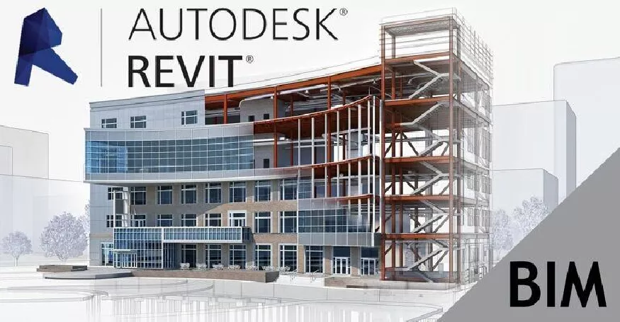
Autodesk Revit has established itself as an essential tool for building and construction professionals. Its ability to create 3D parametric models that integrate project data makes it a preferred solution for Building Information Modeling (BIM). This article explores the essential aspects of data interoperability with Revit, a crucial issue for multidisciplinary collaboration in construction projects.
History and Evolution of Revit
Revit was originally developed by Charles River Software, founded in 1997 by Leonid Raiz and Irwin Jungreis, former developers of PTC's Pro/Engineer software. Their goal was to bring parametric modeling, common in mechanical CAD, to the building industry. The first version of Revit was launched on April 5, 2000.
The company was renamed Revit Technology Corporation in January 2000, then acquired by Autodesk for $133 million in 2002. This acquisition accelerated the development and improvement of the software. The name "Revit" is actually a contraction of "Revise-Instantly," reflecting the software's ability to update all linked elements when a modification is made to one part of the model.
Over the years, Revit has been enriched with new features:
- 2005: Introduction of Revit Structure
- 2006: Launch of Revit MEP
- 2011: Release of Dynamo in beta version
- 2012: Introduction of Revit LT, a lighter version of the software
In 2025, more than 14,302 companies worldwide use Revit as a CAD tool, with 1,610 specifically in the field of architecture. This massive adoption demonstrates its dominant position in the AEC (Architecture, Engineering and Construction) sector.
Revit's Geometric Engine and Its Specificities
Revit's geometric engine is based on specific technical choices that distinguish it from other CAD systems. Unlike software such as Inventor or AutoCAD, Revit uses parameterized curves and surfaces to represent geometric edges and faces respectively.
A notable peculiarity concerns the representation of cylindrical shapes: in Revit, a complete cylindrical face is generally divided into two half-cylinders. This approach results from a deliberate choice in the design of Revit's geometric core to avoid ambiguities in surface parameterization.
Developer John Mitchell from the Revit team explains this technical choice:
"Revit uses parameterized curves and surfaces to represent the geometry of edges and faces. For example, a spherical surface essentially uses latitude and longitude as coordinates. By prohibiting closed edges and faces, we represent the sphere using two hemispherical faces, which eliminates any ambiguity when determining coordinates."
This approach, although it may seem counter-intuitive for users accustomed to other CAD systems, offers advantages in terms of consistency and reliability of the parametric model.
Exchange Formats Supported by Revit
Revit supports a wide range of exchange formats to facilitate interoperability with other CAD and BIM applications. This flexibility allows AEC professionals to integrate Revit into various workflows and exchange data with different disciplines.
Standard Import and Export Formats
Revit supports the following formats for data import and/or export:
- DGN (MicroStation Design File): Used to exchange data with Bentley MicroStation users
- DWF/DWFX (Design Web Format): Lightweight format developed by Autodesk for sharing and visualization
- DWG/DXF (AutoCAD Drawing): AutoCAD native formats, widely used in the industry
- IFC (Industry Foundation Classes): Essential open format for BIM interoperability
- SAT (ACIS SAT): File format for solid geometry exchange
- SKP (SketchUp): SketchUp native format, used for importing architectural concepts
Formats Added in Revit 2023
Version 2023 extended interoperability capabilities with the addition of three important formats:
- AXM (FormIt): Autodesk FormIt native format, now supported for import and direct linking in Revit
- OBJ (Wavefront Object): Versatile 3D exchange format, initially supported for import in version 2022.1, then for linking in version 2023
- STL (Stereolithography): Standard format for 3D printing and additive manufacturing
Format Added in Revit 2025
- STEP/STP : ISO standard format widely used in mechanical and manufacturing industries, newly supported in Revit 2025
Recent Developments by Version
Revit 2025
- Improved support for open formats with optimized category mapping for IFC export
- Introduction of support for STEP format (STP), widely used in mechanical and manufacturing industries
- Tracking and visualization of changes in linked models stored on Autodesk Docs, including for IFC and NWC (Navisworks) links
- Enhanced integration with Twinmotion for visualization, with a new "Twinmotion Substitution" parameter
Revit 2023
- Improved workflows between Revit and FormIt Pro with the ability to directly link FormIt files (AXM) in Revit
- Better support for placement and appearance of imported CAD file formats
- New "Allow cut in views" parameter for 3D elements from CAD files
- Advanced features for mapping standard IFC attributes to model elements
Revit 2022
- IFC4 certification for architecture and structure export, making Revit the first software to support IFC4 reference view export for multiple disciplines
- Improved interoperability with Inventor, allowing export of Inventor assemblies to RVT files
These developments demonstrate Autodesk's ongoing commitment to improving Revit's interoperability with other platforms and formats, thus facilitating collaborative workflows in the AEC sector.
IFC4 Format Support: A Decisive Step Towards Complete Interoperability
The IFC (Industry Foundation Classes) format is essential for BIM interoperability, and Revit offers complete support for this format. For imports, Revit supports IFC files based on IFC4, IFC2x3, IFC2x2, and IFC2x standards. For exports, it supports IFC4, IFC2x3, and IFC2x2 standards.
Advantages of IFC4
IFC4 represents a major advancement over previous versions, with significant improvements:
- File size reduction : IFC4 offers much more efficient ways to store geometry, both for meshes and parametric shapes. For example, an IFC file produced from Revit of a single object weighing 16,098 kB can be reduced to 4,487 kB when re-exported in IFC4, without any loss of geometric detail.
- Better mesh representation : The new support for tessellated forms allows a much more efficient description of meshes compared to the faceted BREPs of IFC2X3.
- Improved parametric geometry support : IFC4 enhances Revit's ability to export parametric geometry, thus preserving the intelligence of the model.
IFC Export Tools in Revit
Autodesk regularly updates Revit's IFC exporter to integrate new features and fix bugs. The IFC Export Alternate UI offers additional flexibility in choosing export options. Both tools are available on the Autodesk App Store and must be downloaded and installed manually.
For English-speaking users, the "IFC Exporter for Revit" provides a set of parameter sets that can be used directly for exports. It is possible to add, delete, or modify an existing parameter set to adapt it to the specific needs of the project.
CAD Interop Solutions for Revit Interoperability
3DViewStation: Advanced Visualization and Analysis of Revit Models
3DViewStation is a high-performance solution distributed by CAD Interop that allows visualization and analysis of CAD models, including those created with Revit, without requiring installation of the original software. This solution offers several advantages for professionals working with Revit data:
- Fast and lightweight visualization of complex BIM models
- Geometric analysis tools to verify model quality
- Measurement and section features to examine different parts of the model in detail
- Ability to combine data from different sources for a global view of the project
- Export to various formats to facilitate communication with stakeholders who do not have BIM software
3DViewStation integrates perfectly into BIM workflows and is an ideal complement to Revit for teams that need to share and analyze complex models.
SimLab for Immersive Experiences from Revit Models
SimLab, also distributed by CAD Interop, is an innovative solution that transforms Revit models into immersive experiences. This platform facilitates:
- The creation of virtual reality (VR) environments from Revit models
- The development of augmented reality (AR) applications to visualize projects in their real context
- The development of interactive presentations for clients and stakeholders
- The simulation of space occupation and usage scenarios
- The optimization of designs through a more intuitive understanding of 3D spaces
SimLab transforms Revit's technical data into powerful communication tools, thus facilitating collaboration between designers, clients, and end users.
Revit Interoperability Tips
Optimizing DWG Exports
To ensure optimal conversion to DWG format:
- Configure layers and line styles in Revit before export
- Use project-specific export settings to maintain consistency
- Check the selected DWG version to ensure compatibility with recipients
Improving IFC Exchanges
To maximize the quality of IFC exchanges:
- Use the alternative IFC export UI for more precise control
- Create custom export parameter sets for different project types
- Verify that all elements are correctly mapped to the appropriate IFC classes
- Prefer using IFC4 to reduce file size and improve geometric accuracy
Managing Complex Assemblies
When transferring models with complex assemblies:
- Check the assembly hierarchy after import/export
- Use dedicated export views to precisely control what is shared
- Document relationships between components that might be affected during conversions
Best Practices for Exchanging Revit Models
Model Preparation
Before sharing Revit models:
- Clean the model of temporary or non-essential elements
- Check the consistency of schedules and annotations
- Ensure all links are properly managed
- Use the interference checking tool to identify and resolve potential conflicts
Data Structuring
Good data structuring facilitates interoperability:
- Organize the model with logical sub-projects
- Use well-named and documented families and types
- Apply consistent project standards to facilitate interpretation by other users
- Properly populate metadata for better utilization by other software
Exchange Documentation
For effective collaboration:
- Document software versions used
- Specify exchange formats and applied export parameters
- Clearly identify known limitations or elements requiring special attention
- Establish a BIM exchange protocol with all project stakeholders
Conclusion
CAD data interoperability with Revit is a crucial issue for professionals in the AEC sector. Revit's import and export capabilities, particularly with the IFC4 format, offer extensive possibilities for interdisciplinary collaboration. Solutions offered by CAD Interop, such as 3DViewStation and SimLab, enrich this ecosystem by providing complementary functionalities for visualization, analysis, and creation of immersive experiences.
By applying the best practices and tips presented in this article, Revit users can optimize their data exchange workflows and thus improve the overall efficiency of their BIM projects. Mastery of these technical aspects constitutes a significant competitive advantage in a sector where digital collaboration has become essential.
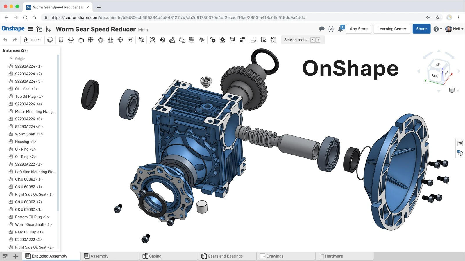
OnShape is a computer-aided design (CAD) software entirely cloud-based, offering a complete 3D modeling experience for product design, development, and manufacturing. It stands out with its SaaS (Software as a Service) approach that allows access to the software from any device with an internet connection, without prior installation or local maintenance.
Founded in 2012 by Jon Hirschtick, John McEleney, and Dave Corcoran - all former SolidWorks executives - OnShape revolutionized the CAD world with its cloud-native approach. Here are the key milestones in its development:
- March 2015: Launch of the public beta version, including OnShape for iPhone
- August 2015: Release of the OnShape application for Android
- December 2015: Full commercial launch and opening of the OnShape App Store
- May 2016: Introduction of FeatureScript, an open-source programming language to create and customize CAD features
- November 2019: Acquisition by PTC for $470 million
- February 2024: iOS support for Apple Vision Pro, enabling real applications of CAD models in augmented reality
Native Format and Geometric Engine
Proprietary Data Format
OnShape uses a proprietary file format called "OnShape Document," stored exclusively in the cloud. This format contains all information related to the 3D model, including its geometry, material properties, and complete design history.
Parasolid: OnShape's Technological Core
OnShape relies on the Parasolid geometric engine, developed by Siemens PLM Software, one of the most robust and widespread kernels in the CAD industry. This strategic choice allows OnShape to benefit from proven technology used by many other professional CAD systems.
The Parasolid kernel is responsible for essential geometric operations in OnShape:
- Precise modeling of B-Rep (Boundary Representation) solids and surfaces
- Complex Boolean operations (union, subtraction, intersection)
- NURBS curves and surfaces management
- High-precision topology calculations and tessellation
- Complex assembly manipulation
This engine also enables native compatibility with Parasolid files (.x_t and .x_b), facilitating data exchange with other systems using the same kernel such as SolidWorks, NX, and Solid Edge.
OnShape's Interoperability Capabilities
OnShape stands out with its complete support for CAD data exchange standards. The system integrates powerful converters allowing import and export of a wide range of native and neutral formats. This flexibility greatly facilitates project migration from traditional CAD systems and collaboration with partners using different platforms.
OnShape uses CrossCad/Ware technology from Datakit to ensure 3D CAD data interoperability. This solution is integrated into the cloud platform to enable efficient translation between the cloud environment and traditional CAD systems.
Part Formats Supported by OnShape
| Format | Import | Export |
|---|---|---|
| Parasolid B-rep (.x_t, .x_b) | v10.0 to v37.0 | v25.0 to v37.0 |
| Parasolid mesh | v28.0 to v37.0 (visualization only) | v28.0 to v37.0 |
| Parasolid mixed model | v32.0+ | ✓ |
| ACIS (.sat) | up to 2023 1.0 | Version 5 |
| STEP (.stp, .step) | AP203, AP214, AP242 (geometry and colors) | AP203, AP214, AP242 |
| IGES (.igs, .iges) | up to 5.3 | 5.3 |
| CATIA v4 | 4.15 to 4.24 | ✗ |
| CATIA v5 | R7 to R33 | ✗ |
| CATIA v6 | R2010x to R2025X | ✗ |
| SOLIDWORKS (.sldprt) | 1999 to 2025 | 2006 |
| Inventor | 9 to 2025 | ✗ |
| Pro/ENGINEER, Creo | Pro/E 2000i to Creo Parametric 11.0 | ✗ |
| JT (.jt) | up to 11.0 | up to 11.0 |
| Rhino (.3dm) | versions 2 to 8 | versions 7 and 8 |
| STL (.stl) | ✓ (visualization only) | ✓ |
| OBJ (.obj) | ✓ (visualization only) | ✓ |
| NX | UG15.0 to NX 2406 Series | ✗ |
| Solid Edge (.par, .psm) | 10 to 2025 | ✗ |
| glTF (.gltf) | version 2.0 | ✓ |
| 3MF | ✓ | ✓ |
| Collada (.dae) | ✗ | 1.4.1 |
| PVZ (.pvz) | ✗ | version 8.0 |
Assembly Formats Supported by OnShape
| Format | Import | Export |
|---|---|---|
| Parasolid B-rep (.x_t, .x_b) | v10.0 to v37.0 | v25.0 to v37.0 |
| Parasolid mixed models | ✗ | ✓ |
| ACIS (.sat) | up to 2023 1.0 | Version 5 |
| STEP (.stp, .step) | AP203, AP214, AP242 | AP203, AP214, AP242 |
| IGES (.igs, .iges) | ✗ | 5.3 |
| CATIA v4 | 4.15 to 4.24 (via .zip) | ✗ |
| CATIA v5 | R7 to R33 (via .zip) | ✗ |
| CATIA v6 | R2010x to R2025X (via .zip) | ✗ |
| SOLIDWORKS | 1999 to 2025 (via Pack and Go .zip) | ✗ |
| Inventor (.iam) | 9 to 2025 | ✗ |
| Pro/ENGINEER, Creo | Pro/E 2000i to Creo Parametric 11.0 | ✗ |
| JT (.jt) | up to 11.0 | up to 11.0 |
| Rhino (.3dm) | versions 2 to 8 | ✗ |
| NX | UG15.0 to NX 2406 Series | ✗ |
| Solid Edge | 10 to 2025 (via .zip) | ✗ |
| STL | ✗ | ✓ |
| glTF (.gltf) | version 2.0 | ✓ |
| 3MF | ✓ | ✓ |
| OBJ (.obj) | ✗ | ✓ |
| Collada (.dae) | ✗ | 1.4.1 |
| PVZ (.pvz) | ✗ | version 8.0 |
Drawing Formats Supported by OnShape
| Format | Import | Export |
|---|---|---|
| AutoCAD (.dwg) | up to 2018 | Release 11-14, 2000-2018 |
| DXF (.dxf) | up to 2013, 2018 | Release 11-14, 2000-2018 |
| DWT (.dwt) | 2013, 2018 | 2013, 2018 |
| SVG | ✗ | ✓ |
| PNG | ✗ | ✓ |
| JPEG | ✗ | ✓ |
Non-CAD Formats Supported by OnShape
| Format | Import | Export |
|---|---|---|
| .mp4 | ✓ | ✗ |
| .png | ✓ | ✗ |
| .jpg/jpeg | ✓ | ✗ |
| .svg | ✓ | ✗ |
| .gif | ✓ | ✗ |
| .txt | ✓ | ✗ |
| .md | ✓ | ✗ |
Parasolid is OnShape's preferred import format for obtaining the best conversion results.
Extensions and Integrations
PCB Studio
OnShape includes PCB Studio, a solution that supports bidirectional exchange of printed circuit board (PCB) designs from ECAD systems. By using standards specifically designed for interoperability, such as Intermediate Data Format (IDF), Incremental Design Exchange (IDX), and EAGLE files (BRD), it is possible to exchange data in both directions between ECAD solutions and OnShape without loss of relevant geometric detail.
PCB Studio builds a shared, searchable, always-synchronized library of electrical components that helps teams reuse components to save time. It also creates a simplified OnShape model for each new component in the ECAD data.
SimLab Composer - Virtual Reality Solution for OnShape
SimLab Composer is integrated with OnShape, meaning that cloud-based documents can be imported directly into SimLab Composer from OnShape's cloud storage. This solution, distributed by CAD Interop, is designed to create interactive visualizations and output variations from your designs.
Key features of SimLab Composer with OnShape:
- Virtual Reality (VR): Easy creation of advanced VR experiences from OnShape models in minutes
- Rendering: Rendering designs in a very fast and realistic progressive engine with different outputs (images, videos and animations, 360° images)
- 3DPDF: Share work by embedding 3D views in PDF files for complete communication
- Texture Baking: Applying materials and texture baking for a realistic appearance when viewing designs
- Mechanism Simulation: Ability to simulate mechanisms created in OnShape
SimLab Composer supports the latest version of OnShape and works on Windows and Mac.
Best Practices for Data Exchange with OnShape
Recommendations for Importing into OnShape
To maximize conversion quality when importing data into OnShape:
- Prefer Parasolid formats (.x_t, .x_b) for best results
- For complex assemblies, use the "Pack and Go" function for SOLIDWORKS
- For other CAD systems, create a ZIP file with the same name as the main assembly
- Check for absence of special characters in filenames
- Use the "Import appearances" option to preserve visual properties
Optimization for Exporting from OnShape
When exporting to other CAD systems:
- For maximum compatibility, prefer STEP AP242 or Parasolid formats
- Use the "Derived" functionality to share simplified models while protecting your intellectual property
- Export in STEP AP242 to preserve colors and metadata
Competitive Advantages of OnShape Interoperability
OnShape's approach to interoperability offers several strategic advantages:
- Optimized Workflows: Reduction of conversion steps when exchanging with different CAD systems
- Cost Reduction: Elimination of third-party conversion software for most formats
- Accelerated Product Development: Facilitated collaboration between teams using different tools
- Enhanced Flexibility: Adaptability to varying requirements of partners and clients
- Simplified Integration: Seamless connection with existing PDM/PLM systems
The robustness of OnShape's interoperability capabilities makes it an ideal solution for companies working in complex multi-CAD environments, where reliable and accurate conversion of 3D data is essential to project success.
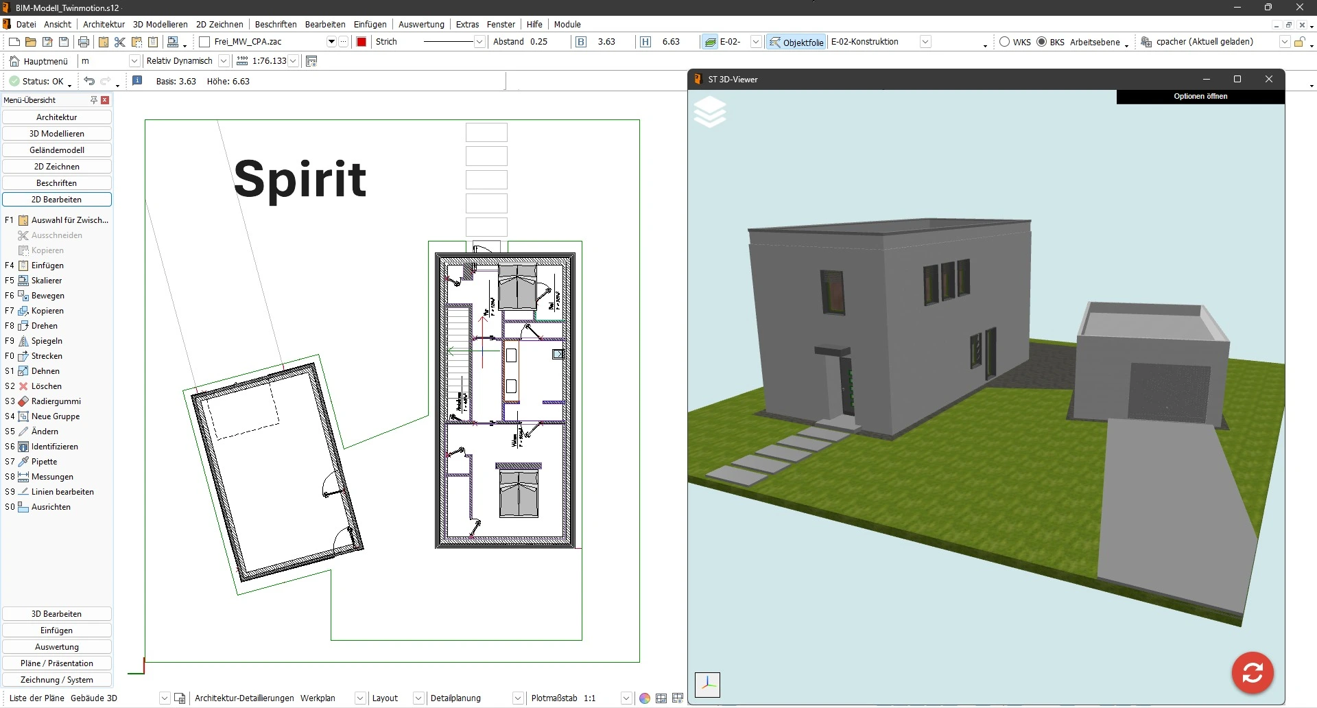
Table of Contents
- Presentation of Spirit Software and its Position in the CAD Ecosystem
- History and Evolution of Spirit Data Exchange Capabilities
- Technical Architecture and Geometric Engine of Spirit
- Native and Exchange Formats Supported by Spirit
- Interoperability Solutions Distributed by CAD Interop for Spirit
- Best Practices for Optimizing Spirit Data Exchange
- Specific Challenges and Solutions for Spirit Interoperability
- How to Integrate Spirit into a Long-Term Archiving Strategy
- Frequently Asked Questions about Spirit Interoperability
Technical data exchange between different CAD systems represents a major challenge for engineering and design companies. Spirit software, developed by Softtech, offers significant but often overlooked interoperability capabilities. This article presents a comprehensive analysis of Spirit's data exchange functionalities and proposes solutions to optimize the interoperability of your models in a multi-CAD environment.
Presentation of Spirit Software and its Position in the CAD Ecosystem
Spirit is a 2.5D computer-aided design (CAD) software developed by Softtech. 2.5D (also called two-and-a-half-D or pseudo 3D) refers to design technologies that are halfway between 2D and 3D. This software is particularly suited for architectural and civil engineering projects, offering a BIM (Building Information Modeling) solution that allows architects, engineers, and designers to create models with limited depth dimension.
Unlike complete 3D CAD systems, Spirit distinguishes itself with its 2.5D approach that offers users the ability to work using several methods:
- Traditional 2D drawing with extrusion elements
- 2.5D modeling with depth management
- Component-oriented design (particularly useful for the BIM approach)
What makes Spirit particularly interesting in a CAD interoperability context is its ability to integrate into heterogeneous workflows, while recognizing its technical limitations compared to complete 3D systems.
History and Evolution of Spirit Data Exchange Capabilities
The development of Spirit is part of a constant improvement approach based on user feedback and the expertise of Softtech employees, many of whom have practical experience as architects, planners, or engineers. This "from practice" approach has influenced the evolution of the software's interoperability capabilities.
Over the years, Spirit has significantly improved its exchange interfaces to meet the growing demands for collaboration in the industry. The optimization of the IFC (Industry Foundation Classes) interface demonstrates this commitment to implementing a true "open BIM," although developers recognize that the path to perfect interoperability is still long.
Notable improvements include:
- Continuous refinement of the IFC interface
- Optimization of IFC model representation
- Significant improvement in graphic exports
- Development of direct exports to specific formats such as SketchUp 3D
This constant evolution positions Spirit as a committed player in resolving CAD interoperability issues that occur "recurrently and at all stages of a product's lifecycle."
Technical Architecture and Geometric Engine of Spirit
Spirit relies on a technical architecture adapted to its 2.5D nature, which directly influences its CAD data exchange capabilities.
Modeling capabilities and data representation:
Spirit manages several geometric data representations, including:
- Extended 2D models with depth information (2.5D)
- Mesh models for export to formats like STL
- Limited parametric data adapted to architectural design
This 2.5D approach directly influences interoperability possibilities, as the software does not manipulate complete volumetric models like 3D CAD systems do. Spirit also seems to support specialized architectural modeling, as indicated by the ZAC extension (Spirit Architectural Component).
The software's flexibility in terms of interoperability remains one of its strengths in its market segment, allowing users to exchange data with other applications, taking into account the inherent limitations of 2.5D modeling.
Native and Exchange Formats Supported by Spirit
Format support is a key element of CAD interoperability. Spirit distinguishes itself through its compatibility with several file formats, both for import and export, although more limited than complete 3D CAD systems.
Spirit native formats:
| Extension | Description | Usage |
|---|---|---|
| .SPIRIT | Main format for Spirit drawings | Native model saving |
| .ZAC | Spirit Architectural Component | Specific architectural components |
| .BT! | BitSpirit Incomplete Download File | Temporary files |
| .TEW | Wrestling Spirit | Specialized format |
Standard formats for import/export:
| Format | Import | Export | Main Use |
|---|---|---|---|
| DWG/DXF | ✓ | ✓ | Collaboration with AutoCAD users |
| STL | ✓ | ✓ | 3D printing, rapid prototyping |
| SketchUp | ✗ | ✓ | Sharing with construction professionals |
| IFC | ✓ | ✓ | BIM exchange (Building Information Modeling) |
It is important to note that Spirit, as a 2.5D software, cannot import or export advanced 3D formats like STEP or ACIS. This limitation is inherent to its technical architecture and determines the possible interoperability scenarios.
Interoperability Solutions Distributed by CAD Interop for Spirit
CAD Interop offers several solutions specially designed to improve the interoperability of Spirit data in various professional contexts. These tools allow users to fully leverage their Spirit models beyond the limits of the native software.
SimLab Composer for Spirit:
The flagship solution distributed by CAD Interop for Spirit users is SimLab Composer, a powerful integration that transforms CAD models into interactive and immersive experiences. This plugin offers:
- Advanced visualization of Spirit designs in interactive environments
- Creation of immersive experiences from 2.5D technical models
- Use of complete SimLab Composer functionalities directly with Spirit data
This integration perfectly meets the needs for CAD visualization without a complete CAD license, thus enabling extended collaboration with partners and clients.
Other compatible solutions:
CAD Interop also offers other software compatible with Spirit files, particularly for:
- Conversion and simplification between Spirit and other CAD formats via intermediate formats
- Validation and verification of the quality of exchanged models
These tools are part of the global approach to improving CAD interoperability promoted by CAD Interop, aiming to overcome data exchange challenges that occur "at all stages of a product's lifecycle."
Best Practices for Optimizing Spirit Data Exchange
Effective exchange of Spirit data requires the adoption of certain best practices to ensure the integrity and quality of shared models, taking into account the 2.5D nature of the software.
Recommended export strategies from Spirit:
For architectural and BIM projects, prioritize:
- IFC export for BIM data exchange
- DWG/DXF export for collaboration with AutoCAD users
- STL export for physical modeling needs
These approaches take into account the limitations of Spirit as 2.5D software and optimize exchange with other systems.
Validation before Spirit data exchange:
Before any Spirit data exchange, it is essential to:
- Check the quality of the model to detect possible geometric errors
- Test the export in the target format to confirm the preservation of critical data
- Compare the exported model with the original model to identify differences
These validation steps ensure that your partners will receive usable data that meets your expectations.
Adaptation to specific Spirit data exchange needs:
The export must be adapted to the intended use of the model:
- For technical documentation: prioritize DWG/DXF formats
- For BIM collaboration: IFC format with preliminary verification
- For 3D printing: STL export with optimized parameters
- For feasibility studies: STL export for physical model printing
A preliminary analysis of the recipient's needs allows choosing the most appropriate exchange format, while taking into account the limitations of 2.5D.
Specific Challenges and Solutions for Spirit Interoperability
Spirit data interoperability presents specific challenges related to its 2.5D nature that require adapted solutions.
Common interoperability challenges with Spirit:
Spirit users may encounter several obstacles during data exchange:
- Intrinsic limitation related to 2.5D modeling versus complete 3D
- Variable interpretation of IFC data between different BIM platforms
- Inability to exchange with advanced 3D formats like STEP
- Preservation of specific metadata and attributes
These challenges are amplified by the very nature of Spirit as a 2.5D solution in a world where complete 3D systems are widely used.
Effective solutions and workarounds for exchanging Spirit data:
To overcome these challenges, several approaches can be adopted:
- For exchanges with 3D CAD systems:
- Use compatible intermediate formats (like DXF)
- Accept the limitation of exchanges to basic geometric elements
- Consider specialized third-party conversion solutions
- For BIM and IFC issues:
- Stay informed about continuous improvements to Spirit's IFC interface
- Systematically validate exchanged IFC models in target platforms
- Document known limitations for each type of exchange
- For sensitive data protection:
- Use DEXcenter to secure the transmission of Spirit files
- Implement an exchange registry to track data usage
These solutions significantly mitigate common interoperability problems and optimize workflows involving Spirit data, despite the inherent limitations of 2.5D modeling.
How to Integrate Spirit into a Long-Term Archiving Strategy
Long-term archiving of CAD data represents a major challenge for companies whose projects have an extended lifecycle. For Spirit users, adopting an adapted archiving strategy is essential.
Recommended formats for archiving Spirit data:
For effective archiving of Spirit models, prioritize:
- IFC format for BIM projects
- PDF (2D) formats for visual documentation
- A combination of native and DWG/DXF formats for maximum security
This multi-format approach ensures that your Spirit data will remain accessible even after the evolution of CAD systems.
Archive validation:
Archiving is not limited to storage; it also requires rigorous validation:
- Certify that the archived model faithfully represents the original model
- Regularly check the accessibility of archived data
- Document the conversion processes used for archiving
These validation practices are essential to ensure the reliability of archives and their future usability.
Frequently Asked Questions about Spirit Interoperability
What are the main limitations of Spirit in terms of 3D interoperability?
As 2.5D software, Spirit cannot import or export advanced 3D formats like STEP. This fundamental limitation restricts exchanges to simpler formats like DWG/DXF, STL, or IFC, and strongly influences the interoperability strategies to adopt.
How to ensure the best compatibility between Spirit and common CAD systems?
To optimize compatibility, prioritize DWG/DXF export for exchanges with other CAD systems. Systematically test your exports in the target system and document best practices specific to each partner platform, taking into account the limitations of 2.5D.
Is it possible to convert a Spirit model into a complete 3D model?
Converting a Spirit 2.5D model into a complete 3D model presents inherent limitations. Third-party tools can help with this transition, but expect to have to rebuild certain parts of the model.
How to effectively manage BIM projects with Spirit and other software?
For BIM projects, focus on optimizing IFC exchanges, the preferred format for BIM interoperability. Spirit continuously works on improving its IFC interface, but systematic validation of exchanges remains necessary to ensure the preservation of critical information between different platforms.
Spirit data interoperability, though limited by its 2.5D nature, can be significantly improved through a combination of best practices, specialized tools, and adapted exchange formats. The solutions offered by CAD Interop, particularly SimLab Composer, provide powerful options to fully exploit the potential of Spirit models in a multi-CAD environment, while recognizing and compensating for its technical limitations.
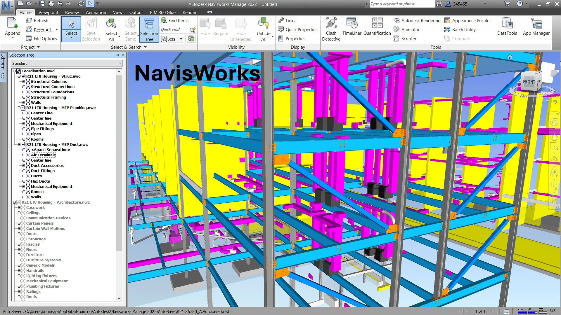
Navisworks is a 3D design review software developed by Autodesk that plays a crucial role in the CAD interoperability ecosystem. As a coordination and project review tool, it allows combining 3D models from various sources and formats to create a complete and coherent project model. Let's discover in detail how Navisworks facilitates CAD data exchange and optimizes collaborative workflows in construction projects.
History and uses of Navisworks software
Acquired by Autodesk, Navisworks has established itself as one of the most reliable review and coordination tools used by construction project managers and VDC (Virtual Design and Construction) professionals. Its development was guided by the need to create a common platform where different models designed on various platforms can be analyzed and coordinated.
Main uses and benefits
Navisworks is primarily used for:
- Detecting and resolving conflicts between different disciplines (structure, MEP, architecture)
- Coordinating complex projects
- Construction simulation and planning (4D)
- Project visualization for client presentations
- Estimation and quantification for quotes (5D)
The software offers considerable advantages in terms of collaboration, including:
- Early detection of conflicts before construction
- Complete project visualization
- Temporal simulation of the construction process
- Accurate project estimation
- Improved risk management
- Streamlined communication between stakeholders
The Navisworks geometric engine
The Navisworks geometric engine is specially designed to optimize rendering and spatial analysis of complex models. It uses simple tessellated geometry that enhances performance when handling large models.
Structure of the geometric engine
Navisworks employs a spatial graph for all spatially oriented operations such as rendering, selection, collision detection, and clash detection. The leaves are self-contained instances comprising a bounding box, transformation, material, and geometry definition, all stored in a format optimized for rendering.
To efficiently support spatial queries, Navisworks uses a hierarchy of spatial bounding boxes (a variant of R-tree). This structure allows the software to quickly process large and complex models.
Data organization
The Navisworks data model is written in separate streams, in the order they are typically read:
- The logical scene graph
- The spatial hierarchy
- The set of instances
- Separate streams for each functionality with its own metadata (clash tests, saved viewpoints, selection sets, etc.)
This organization not only allows loading data on demand but also adding new functionalities without having to modify the file format, thus ensuring compatibility with previous versions.
Navisworks native file formats
Navisworks uses three native file formats, each with specific characteristics and uses:
NWD Format
An NWD file contains all model geometry along with Navisworks-specific data, such as review annotations. This format can be considered as a snapshot of the current state of the model. NWD files are very lightweight, compressing CAD data up to 80% of their original size.
NWF Format
An NWF file contains links to the original native files (listed in the selection tree) along with Navisworks-specific data. No model geometry is saved with this format, which makes an NWF file considerably smaller than an NWD.
NWC Format (cache files)
By default, when you open or append native CAD files or laser scans in Navisworks, a cache file is created in the same directory and with the same name as the original file, but with the .nwc extension. These files are smaller than the original files and speed up access to frequently used files.
Supported CAD and laser scan formats
Navisworks supports a wide range of CAD and laser scan file formats, making it an extremely versatile tool for data interoperability.
CAD formats supported in NavisWorks 2025
Navisworks can open many native CAD formats without requiring the corresponding CAD applications to be installed on your machine:
- CATIA V4: .model, .session, .exp, .dlv3
- CATIA V5: .CATPart, .CATProduct, .cgr
- CIS/2: .stp
- DWF: .dwf, .dwfx, .w2d
- DWG/DXF: .dwg, .dxf
- FBX: .fbx
- IFC: .ifc
- IGES: .igs, .iges, .ige
- Inventor: .ipt, .iam, .ipj
- JT: .jt
- MicroStation Design: .dgn, .prp, .prw
- NX: .prt
- OBJ: .obj
- Parasolid: .x_b, .x_t, .xmt_txt
- PDF: .pdf
- PDS: .dri
- Pro/ENGINEER: .prt, .asm, .g, .neu
- Revit: .rvt, .rfa, .rte
- Rhino: .3dm
- RVM: .rvm
- SAT: .sat, .sab, .smt, .smb
- SketchUp: .skp
- SmartPlant 3D: .vue
- SolidWorks: .prt, .sldprt, .asm, .sldasm
- STEP: .stp, .step, .stpz, .ste
- STL: .stl, .stla, .stlb
- 3D Studio: .3ds, .prj
Laser scan formats supported in Navisworks 2025
Navisworks can also open various laser scan file formats:
- ASCII Laser File: .asc, .txt
- Leica: .pts, .ptx
- ReCap: .rcs, .rcp
Navisworks versions and types
Autodesk offers three distinct versions of Navisworks, each tailored to specific needs in the design and construction industry:
- Navisworks Freedom (beginner level): This is the simplest and free version of the software, often called the Navisworks "viewer." It allows viewing Navisworks files in .NWD and .DWF formats. Although it lacks the advanced features of paid versions, it offers valuable functionality that allows stakeholders to navigate and examine the model without modifying it.
- Navisworks Simulate (intermediate level): This intermediate version offers more advanced features than Freedom, particularly allowing 4D simulations by integrating construction schedules with 3D models.
- Navisworks Manage (advanced level): This is the most comprehensive version, designed to offer complete project review solutions to design and construction professionals. It provides advanced tools for 5D analysis, interference analysis, and spatial coordination.
Plugins and extensions for Navisworks
Navisworks' open architecture allows the use of numerous plugins developed by Autodesk and third parties to extend its functionality. These plugins can be installed automatically or manually depending on their type.
Popular paid plugins
- Navistools Quantification: An advanced plugin that provides powerful tools for surveying and extracting quantities from Navisworks models, crucial for accurate estimation of materials and costs.
- Advanced Work Packaging (AWP): This plugin helps streamline project delivery by breaking down complex tasks into smaller, manageable work packages, particularly useful in large construction projects.
Essential free plugins
- Asite 3D Repo: Enhances collaboration by allowing users to directly connect their Navisworks models to the 3D Repo cloud platform, enabling teams to review and manage 3D models in real-time.
- Coordination Add-in for Navisworks: Essential for teams working on complex projects, it allows easy detection and resolution of conflicts, ensuring that different project elements work together harmoniously.
- Navisworks Plugin for Revit: Ensures smooth transfer of models between Revit and Navisworks, allowing users to import Revit models into Navisworks for detailed review and analysis.
- Navisworks VR Plugin: Allows users to experience 3D models in a fully immersive environment, helping clients and stakeholders better understand the project.
- Enscape for Navisworks: Brings high-quality real-time rendering to your BIM workflow, allowing instantaneous visualization of changes, ideal for project presentations or meetings with clients.
Integration with Autodesk Construction Cloud
Navisworks integrates seamlessly with Autodesk Construction Cloud, offering additional capabilities for BIM management and collaboration. This integration allows for better management of construction data throughout the project lifecycle, ensuring smooth communication between all stakeholders.
CAD Interop solutions for Navisworks
CAD Interop distributes several software solutions to visualize and convert Navisworks files, thus enhancing interoperability and collaboration in your projects.
3DViewStation for visualizing and analyzing Navisworks models
3DViewStation is a powerful solution for visualization, analysis, and conversion of CAD data, including Navisworks models. Its advanced features allow users to:
- Quickly visualize complex 3D models
- Perform precise measurements
- Analyze geometries to detect potential problems
- Create sections and exploded views
- Export to various formats for seamless collaboration
Thanks to its intuitive interface and optimized performance, 3DViewStation is an ideal complement to Navisworks for teams that need to efficiently analyze and share CAD models.
SimLab for creating immersive experiences from Navisworks models
SimLab allows transforming your Navisworks models into immersive virtual reality experiences, offering new perspectives for project presentation and analysis. With SimLab, you can:
- Directly convert Navisworks models into VR environments
- Organize interactive virtual tours
- Simulate real usage scenarios
- Facilitate decision-making through immersive visualization
- Improve communication with clients and stakeholders
This solution adds an extra dimension to your Navisworks projects, allowing a more intuitive and in-depth understanding of designs.
Best practices for exchanging Navisworks models
To maximize the efficiency and reliability of data exchanges with Navisworks, here are some recommendations:
Preparing models for exchange
- Use NWC files to speed up loading times during repeated uses
- Organize your model into logical subsets to facilitate navigation
- Clean up non-essential data before exporting to reduce file sizes
- Check the quality and integrity of models before combining them in Navisworks
Performance optimization
- Use appropriate Level of Detail (LOD) techniques according to project needs
- Leverage Navisworks' caching capabilities for frequently used files
- Divide large models into manageable subsets to improve performance
- Use NWD files for sharing with external partners (contains all necessary data)
Collaboration and coordination
- Establish clear protocols for file naming
- Define common reference points for all models to be combined
- Use DEXcenter to automate and secure CAD data exchanges with partners
- Document the standards and conventions used in the project
Data security
- Take advantage of the secure web environment of solutions like DEXcenter for secure transmission of sensitive proprietary CAD data
- Use data encryption during transfer over the Internet to prevent interception
- Maintain a record of each exchange to validate what was sent to each partner and when
Conclusion
Navisworks represents an essential tool in the CAD interoperability ecosystem, facilitating coordination, review, and analysis of complex construction projects. Its ability to integrate models from various sources, detect potential conflicts, and simulate the construction process makes it a valuable ally for AEC professionals.
The complementary solutions offered by CAD Interop, such as 3DViewStation and SimLab, enhance the Navisworks experience by offering additional capabilities for visualization, analysis, and immersion. For organizations seeking to optimize their CAD data exchange workflows, solutions like DEXcenter provide a secure environment for the transmission and management of Navisworks files.
By following best practices for model exchange and fully exploiting Navisworks' interoperability capabilities, project teams can significantly reduce errors, improve communication, and deliver higher quality projects in shorter timeframes.
Fusion 360 is a CAD software developed by Autodesk that enables 3D design and modeling in various industries such as mechanical engineering, architecture, and engineering. This solution offers advanced features for creating precise 3D models, designing complex shapes, and managing assemblies.
File formats and native compatibility
Fusion 360 primarily uses the F3D format, which preserves all design information including:
- Parts and assemblies
- Sketches and workplanes
- Materials and properties
Other compatible extensions include .f3z, .f2d, .dwg, and .dxf. F3D files integrate seamlessly with other Autodesk solutions (AutoCAD, Inventor) and enable data exchange with SolidWorks, Catia, and Creo.
Technical architecture and geometric engine
Fusion 360 relies on the Autodesk ShapeManager geometric kernel, derived from the ACIS engine. This architecture offers several technical advantages:
- Simultaneous direct and parametric modeling
- Efficient management of complex assemblies
- Flexible and non-linear design history
- Optimal handling of complex surfaces and solid bodies
The cloud-native architecture facilitates centralized storage while enabling export to various standard formats for interoperability.
Interoperability capabilities and data exchange
Supported import formats
Fusion 360 offers wide compatibility for importing files from different CAD platforms:
- Native formats: Autodesk (Alias, Inventor), SolidWorks, Catia V5, NX, Creo, Rhino
- Standard formats: STEP (AP203, AP214, AP242), IGES, Parasolid (XT, XB), SAT/SMT (ACIS)
- 2D formats: DWG, DXF, PDF
- Mesh formats: STL, OBJ, FBX
Supported export formats
To share your designs with other systems, Fusion 360 offers export to:
- Native formats: F3D, F3Z
- Exchange formats: STEP AP242 (including PMI), IGES, SAT
- Manufacturing formats: STL, 3MF, VRML, OBJ
- Documentation: PDF, DWG, DXF
Note that native formats are not backward compatible with older versions of Fusion.
ACIS interoperability and geometric processing
Since ACIS is the common geometric engine for Autodesk software, saving and reading in ACIS format is done without conversion, eliminating geometric interoperability issues.
Extensions and add-on modules optimizing data exchange
Fusion 360 offers several extensions that enhance its interoperability capabilities:
Manufacturing Extension
- Generation of toolpaths for CNC machines
- Export of G-code compatible with different controllers
- Machining simulation and validation
Simulation Extension
- Finite element analysis
- Exchange of results via neutral formats
- Pre-manufacturing validation
Data Management Extension
- Revision and version management
- Access control and collaboration
- Integration with PDM/PLM systems
Rendering and Visualization Extension
- Creation of photorealistic renderings
- Export to virtual reality platforms
- Preparation for 3D printing
Advanced API exploitation for conversion automation
The Fusion 360 API allows programmatic interaction with models, facilitating the automation of exchange and conversion tasks. This functionality is particularly useful for:
- Accessing and modifying model parameters
- Preserving parametric design intent during exchanges
- Creating custom Python scripts for complex conversions
Matrix transformation features enable precise manipulation of assembly components, essential when preparing models before conversion or reconstructing them after import.
Workflow optimization for data conversion
Adequate preparation of models before conversion is crucial to ensure successful exchanges. This preparation involves:
- Evaluating model complexity
- Identifying potentially problematic features
- Selective simplification when necessary
- Analyzing relationships between components and assembly hierarchy
For large assemblies, a structured approach ensures data consistency after transfer.
SimLab: Complete solution for visualization and utilization of Fusion 360 models
SimLab Composer offers a powerful and flexible solution to fully leverage models created in Fusion 360, thanks to a free integration plugin that establishes a dynamic link between the two applications.
Fusion 360 integration plugin
The SimLab plugin for Fusion 360 functions as an intermediate layer between Fusion 360 and SimLab Composer, allowing users to:
- Create an active link automatically synchronizing data between the two platforms
- Modify the model in Fusion 360 and see the changes instantly applied in SimLab Composer
- Retain materials and modifications applied in SimLab during Fusion model updates (using the "retain scene materials" option)
- Support Fusion 2023 and earlier versions, on both Windows and macOS
Main use cases for SimLab with Fusion 360
SimLab significantly extends the visualization and communication capabilities of Fusion 360 models:
- Creation of immersive VR experiences
- Rapid transformation of Fusion models into interactive virtual reality experiences
- Development of VR training without programming using the Training Builder module
- Creation of interactive animations for virtual reality presentations
- Advanced photorealistic rendering
- Generation of high-quality images, videos, and animations
- Creation of 360° images for immersive presentations
- Application of realistic materials and textures via real-time rendering
- Enhanced technical documentation
- Production of 3DPDF files integrating interactive 3D models
- TextureBaking to improve the realism of shared visualizations
- Capture of scene states with different configurations (transformations, visibility, cameras, materials)
- Training and education
- Creation of quizzes and assessments in VR without coding
- Development of interactive educational material
- VR collaboration for up to 30 participants per session
Advantages of SimLab integration for Fusion 360 users
Using SimLab as a complement to Fusion 360 offers several strategic advantages:
- Optimized workflow: Elimination of repetitive imports/exports thanks to the dynamic link between applications
- Significant time savings: Considerable acceleration of the design-rendering process
- Ease of use: Intuitive interface and rapid learning
- Wide compatibility: Support for 18 input formats and 15 output formats for maximum interoperability
- Parallel processing: Ability to work simultaneously on design in Fusion and visualization in SimLab
SimLab Composer integrates perfectly with Fusion 360 to offer a complete pipeline from design to visualization, significantly improving design communication and making it easy to create immersive experiences from CAD models.
Collaboration and collaborative work
Fusion 360 facilitates collaboration via cloud services such as Google Drive, Dropbox, and OneDrive. Teams can:
- Collaborate in real-time on projects
- Share files with team members
- Access designs from any connected device
The evolution of Fusion 360 since its launch in 2013 demonstrates Autodesk's commitment to continuously improving interoperability capabilities, particularly with the progressive integration of the STEP AP242 exchange format.
Data interoperability with Fusion 360 benefits from advances in exchange standards, facilitating communication between different stages of the product development cycle and ensuring data integrity throughout the design and manufacturing process.
Alibre positions itself as an essential tool in the field of Computer-Aided Design (CAD), offering robust solutions for parametric modeling and technical data interoperability. This powerful software enables the creation of precise 3D models and detailed 2D drawings, and is highly regarded by engineers, designers, and manufacturers globally due to its versatility and excellent compatibility with other CAD systems.
File Formats and Interoperability
CAD data interoperability, defined as the ability of 3D software to exchange data seamlessly between different systems, is a fundamental pillar of modern technical collaboration. Alibre excels in this area by supporting a wide range of standardized neutral formats:
- Standard exchange formats: .STEP, .IGES, .SAT, Parasolid (.x_t, .x_b, .xmt_txt)
- Technical drawing formats: .DWG, .DXF, .SVG
- Manufacturing and 3D printing formats: .STL, .OBJ
- Visualization and sharing formats: .JT, .3D PDF
This extensive compatibility allows users to efficiently transfer models and drawings between various CAD applications, facilitating collaboration with partners, clients, and suppliers using other software solutions.
Native Alibre File Extensions
Alibre uses specific file extensions for different types of data, ensuring structured organization of design projects:
- .AD_PRT: 3D parametric part files
- .AD_SMP: Specialized sheet metal part files
- .AD_ASM: Complex assembly files
- .AD_DRW: 2D technical drawing files
- .AD_BOM: Detailed bill of materials files
- .AD_PKG: Alibre Design single-file containers (for easy sharing)
- .AD_GLP: Global configuration files for user preferences
- .AD_PCF: Function catalog files for custom libraries
Compatibility and Backward Compatibility
Recent versions of Alibre Design maintain compatibility with older native file formats, allowing access to models created with previous software versions. However, it's important to note that backward compatibility is not guaranteed; files created with newer versions are generally not readable by older versions of the software. This technical limitation is common to most CAD software and requires appropriate planning for teams working with different versions.
Advanced Interoperability and Collaboration
In an industrial environment where collaboration is essential, Alibre stands out with its advanced CAD interoperability capabilities. The software can import and export native files or convert data from various common CAD systems, including:
- CATIA V5
- Pro/ENGINEER or Creo
- SolidWorks
- Siemens NX
- Autodesk Inventor
- Rhinoceros (Rhino)
This extended interoperability facilitates collaboration in multi-CAD environments, allowing engineering teams to work efficiently despite using different design tools. Users can thus integrate Alibre into existing workflows without compromising data quality or model accuracy.
Solution for Creating Immersive and Collaborative Experiences from Alibre Models
CAD Interop distributes a comprehensive range of complementary software solutions to maximize interoperability and productivity with Alibre files, of which SimLab Composer is a key element.
SimLab Composer for Alibre
SimLab Composer offers a free integration plugin for Alibre, creating an active link between the two software. This plugin allows:
- Automatic synchronization of Alibre models in SimLab Composer
- Rapid creation of virtual reality (VR) experiences from Alibre designs
- Photorealistic rendering of models with a progressive rendering engine
- Generation of interactive 3D PDF files for easy sharing
- Application of textures and materials for realistic rendering
- Simulation of complex mechanisms
Advanced Features of SimLab Composer
In addition to integration with Alibre, SimLab Composer offers:
- Import of various CAD formats
- 3D animation tools
- Creation of interactive catalogs
- Task automation without programming
- Design of interactive quizzes for training
This solution allows Alibre users to significantly extend their visualization, simulation, and collaboration capabilities while maintaining an integrated and efficient workflow.
Alibre Interoperability Tips
Alibre's technical interoperability is accompanied by best practices and lesser-known tips to optimize workflows. These recommendations, derived from user experience and technical forums, allow full utilization of the software's file exchange capabilities.
Optimization of Format Conversions
For exports to .SAT, a common scale factor issue (division by 10) occurs when importing into AutoCAD. The solution is to manually edit the SAT file via a text editor by modifying the 'units per meter' value before reimporting.
When generating .DXF files for plasma cutting, maintaining a 1:1 scale in the drawing view preserves dimensional integrity.
For .STL exports intended for 3D printing, reducing the mesh resolution in the export parameters avoids oversized files (6 GB) and excessive processing times.
Management of Complex Imports
Importing SolidWorks files (.sldprt) requires the presence of all referenced components in the same directory. A tip is to use lightweight mode for assemblies exceeding 1,000 parts, reducing memory load by 40%.
For Rhino models (.3dm), activating the "Merge surfaces" option during import avoids topology errors.
Advanced Automation
The integrated Python script editor allows automation of recurring conversions. A community script allows converting .STL to .STEP in one operation, bypassing the limitations of direct mesh import.
For export batches, setting up predefined profiles with geometric tolerance options (0.001 mm) and removal of empty entities accelerates processing by 70%.
Resolution of Common Problems
In case of corrupted files, Alibre's automatic repair function analyzes defective segments while preserving assembly references.
For version incompatibilities, systematically exporting in STEP AP242 preserves technical metadata during exchanges with obsolete systems.
A recurring problem with Parasolid files (.x_t) is resolved by forcing the binary format (.x_b) for complex assemblies.
Multi-CAD Collaboration
Using the 3D PDF format including PMI (Product Manufacturing Information) allows design review without a CAD license.
For cloud collaborations, integration with Autodesk Drive synchronizes external references while keeping track of modifications.
A little-known tip is to export bills of materials (.AD_BOM) in .CSX for direct integration into ERPs.
Good Archiving Practices
Favoring STEP AP242 with ZIP compression for long-term archiving ensures readability for 15 years according to ISO 10303 standards.
Systematically adding metadata (author, version, units) in the .AD_PKG file properties facilitates traceability.
For sensitive projects, double exporting in JT (visualization) and STEP (exact geometry) covers all reuse needs.
Summary
- Introduction to SolidWorks and Interoperability
- History and Evolution of SolidWorks
- SolidWorks File Formats and Extensions
- Import and Export Capabilities
- SolidWorks MBD and PMI Interoperability Capabilities
- AdvancedInteroperabilityTechnologies
- InteroperabilityBestPractices
- CADInteropSolutions forSolidWorks
- Conclusion
Introduction to SolidWorks and Interoperability
SolidWorks is a Computer-Aided Design (CAD) software developed by Dassault Systèmes, renowned for its ease of use and powerful 2D and 3D modeling capabilities. This system allows engineers and designers to create precise models, complex assemblies, and detailed technical drawings.
CAD data interoperability is a major challenge for companies using SolidWorks, particularly in a multi-CAD collaboration context where different partners, suppliers, and customers may be working with different CAD systems. The ability to reliably and accurately exchange data between these systems is essential for maintaining design integrity and optimizing product development processes.
History and Evolution of SolidWorks
SolidWorks was founded in December 1993 by MIT graduate Jon Hirschtick, who invested $1 million won playing blackjack to fund this project. His vision was to create accessible and affordable 3D CAD software for engineers and designers, running on the Windows platform, which was gaining popularity at the time.
In 1995, the first version of the software, SolidWorks 95, was launched, marking a revolution in the democratization of 3D design. It was the first 3D CAD tool capable of running on a standard desktop PC. Its intuitive interface, robust modeling capabilities, and affordable price quickly attracted the attention of the engineering and design communities.
On July 25, 1997, Dassault Systèmes acquired SolidWorks for $310 million, becoming the largest shareholder and continuing its development to this day. This acquisition by a world leader in CAD and PLM marked the beginning of a new chapter for SolidWorks, benefiting from Dassault Systèmes' extensive resources and global reach.
In the early 2000s, SolidWorks continued to innovate by introducing new features such as as well as web-based collaboration tools and enhanced simulation capabilities. These tools allowed designers to test and refine their models in the same environment.
Today, SolidWorks is used by approximately 7 million engineers and designers worldwide (2023 figures), primarily in the fields of industrial equipment, high technology, life sciences, housing, architecture, engineering, and construction.
SolidWorks File Formats and Extensions
SolidWorks uses several native file formats to store different types of CAD data:
SolidWorks Native Formats:
- .sldprt: Part File SolidWorks
- .sldasm: SolidWorks assembly file
- .slddrw: SolidWorks drawing file
- .slddrt: SolidWorks Template File
These native formats allow you to preserve all parametric information, build history, and design intent created in SolidWorks.
SolidWorks Import and Export Capabilities
SolidWorks offers extensive import and export capabilities through the use of Spatial's InterOp 3D CAD data exchange and interoperability software. This technology allows SolidWorks to support more than 30 neutral and proprietary CAD/CAM file formats.
Table of supported formats by SolidWorks
| Category | Format | Extension | Import | Export | Supported version |
|---|---|---|---|---|---|
| SolidWorks Native Formats | SolidWorks Part | .sldprt | - | - | All versions |
| SolidWorks Assembly | .sldasm | - | - | All versions | |
| SolidWorks Drawing | .slddrw | - | - | All versions | |
| Standard exchange formats | STEP | .stp, .step | ✓ | ✓ | AP203/214 |
| IGES | .igs, .iges | ✓ | ✓ | Version 5.3 | |
| Parasolid | .x_t, .x_b | ✓ | ✓ | Until V32 | |
| ACIS | .sat | ✓ | ✓ | Until R22 | |
| VDAFS | .vda | ✓ | ✓ | Version 2 | |
| Third-party CAD formats | CATIA V5 | - | ✓ | ✗ | Up to V5R27 |
| CATIA Graphics | .cgr | ✓ | ✓ | Up to V5R24 | |
| Pro/E / Creo Part | .prt | ✓ | ✓ | Import up to Creo 8.0, export up to Version 20 | |
| Pro/E / Creo Assembly | .asm | ✓ | ✓ | Import up to Creo 8.0, export up to Version 20 | |
| NX / Unigraphics | .prt | ✓ | ✗ | Version 10 and above, including NX 9 | |
| Inventor Part | .ipt | ✓ | ✗ | Version 11 and higher | |
| Inventor Assembly | .iam | ✓ | ✗ | Version 11 and higher | |
| Solid Edge Part | .par, .psm | ✓ | ✗ | Up to Solid Edge with Synchronous Technology 6 | |
| Solid Edge Assembly | .asm | ✓ | ✗ | Up to Solid Edge with Synchronous Technology 6 | |
| Rhino | .3dm | ✓ | ✗ | Version 4 | |
| CADKey | .prt, .ckd | ✓ | ✗ | Version 19 (prt), Version 21 (ckd) and higher | |
| Formats 2D | AutoCAD Drawing | .dwg | ✓ | ✓ | AutoCAD 2013-2015 (import), AutoCAD 2013 (export) |
| Drawing Exchange Format | .dxf | ✓ | ✓ | AutoCAD 2013-2015 (import), AutoCAD 2013 (export) | |
| Adobe Illustrator | .ai | ✓ | ✗ | - | |
| Mesh formats and 3D printing | STL | .stl | ✓ | ✓ | Version 1 |
| VRML | .wrl | ✓ | ✓ | Up to VRML 2 (VRML 97) | |
| PLY | .ply | ✓ | ✓ | - | |
| Point Cloud | - | ✓ | ✗ | - | |
| Viewing formats and collaboration | 3D XML | .3dxml | ✗ | ✓ | Version 4.2 |
| HOOPS | .hsf | ✗ | ✓ | Version 18.16 | |
| Highly Compressed Graphics | .hcg | ✗ | ✓ | CATIA V5 R9 | |
| IFC (BIM) | .ifc | ✓ | ✓ | IFC2X3 |
SolidWorks MBD and PMI interoperability capabilities
SolidWorks Model Based Definition (MBD) is an add-on that significantly expands SolidWorks' interoperability capabilities, particularly with regard to support for the STEP AP242 format. This module allows you to move from a product definition based on traditional 2D drawings to a fully 3D approach that integrates all manufacturing information directly into the model.
Support for the STEP AP242 format
The STEP AP242 format represents a major evolution in CAD interoperability, combining the features of the AP203 and AP214 formats while adding support for PMI (Product Manufacturing Information). These PMIs include dimensions, geometric tolerances, surface finishes, weld symbols, and other technical annotations directly integrated into the 3D model.
STEP AP242 Export Capabilities:
- Available since SolidWorks 2017 with the MBD module
- Accessible via the "Publish STEP 242 File" command in the MBD tab of the Command Manager
- Allows you to export all 3D and PMI annotations with the geometric model
- Includes the ability to export custom model properties
Specific Export Settings:
- Option to split periodic faces (such as cylindrical faces) to improve export quality
- Ability to export face properties and Edges to preserve important model geometry information
- Control over custom properties to include in the STEP AP242 file
STEP AP242 Import Capabilities:
- Direct import of STEP AP242 files is now supported in recent versions of SolidWorks
- Imported models retain their solid structure, as confirmed by comparative studies between different CAD systems
Benefits of the MBD approach with STEP AP242
Using SolidWorks MBD with the STEP AP242 format offers several significant advantages:
- Elimination of 2D drawings: No need to send both 2D drawings and 3D CAD data to manufacturers, simplifying management Documentation
- Time Saving: Particularly beneficial for complex models with many PMIs
- Reduced Interpretation Errors: Manufacturing information is directly linked to the relevant geometric elements
- Better Interoperability: The STEP AP242 format is considered the best STEP format to use because it is compatible with MBD/MBE (Model-Based Enterprise) workflows
- Universal Viewing: STEP AP242 files can be viewed in eDrawings, allowing partners without SolidWorks to view models with their PMIs
Workflow Integration
SolidWorks MBD integrates seamlessly into existing workflows :
- Step AP242 files can be attached to eDrawings files when publishing, allowing both the lightweight visualization and the complete geometric data to be shared.
- Users can view, extract, or delete STEP attachments directly from eDrawings.
- The MBD module also allows publishing to other formats such as 3D PDF, facilitating information sharing with partners without CAD tools.
The adoption of SolidWorks MBD with STEP AP242 support represents an important step towards the Model-Based Enterprise (MBE), where the 3D model becomes the primary reference for all stages of the product lifecycle.
Advanced Interoperability Technologies in SolidWorks
SolidWorks integrates several advanced technologies to improve the interoperability of CAD data, enabling engineers and designers to collaborate effectively in multi-CAD environments. These sophisticated tools address the complex challenges of exchanging technical data while preserving model integrity.
SOLIDWORKS 3D Interconnect
Introduced in 2017, 3D Interconnect represents a major evolution in SolidWorks' interoperability strategy, replacing legacy conversion capabilities. This technology fundamentally transforms the way users work with third-party CAD data.
Key Features:
- Directly opens native third-party CAD formats (CATIA, NX, Inventor, Creo, Solid Edge) without prior conversion
- Imports proprietary data directly into a SolidWorks assembly while preserving relationships
- Automatically updates the SolidWorks file when the original data changes, maintaining synchronization between systems
- Option to break the link with the imported file to create an independent copy if necessary
- Preserves important metadata such as custom properties and attributes
Workflow Benefits:
- Significantly reduces the time spent on file conversion
- Reduces translation errors Geometric
- Maintains association with source files, enabling dynamic updates
- Simplifies collaboration processes with partners using other CAD systems
3D Interconnect supports many native formats, including CATIA V5 (up to V5-6 R2024), NX (up to NX 2406), Creo (up to Creo 11.0), Solid Edge, and Inventor (up to 2025), as confirmed by recent compatibility data.
3DEXPERIENCE Exchange
This technology bridges the gap between SolidWorks and Dassault Systèmes' 3DEXPERIENCE platform, creating a unified digital ecosystem for design, simulation, and product lifecycle management.
Key Capabilities :
- Two-way data synchronization between SolidWorks and the 3DEXPERIENCE platform
- Secure cloud-based design sharing with version control
- Access to the 3DEXPERIENCE platform's advanced collaborative tools
- Centralized management of technical data and engineering processes
This integration allows geographically dispersed teams to work simultaneously on the same projects, accelerating product development cycles.
ScanTo3D
ScanTo3D is an add-on to SolidWorks Premium that transforms scanned data into usable CAD models. This technology is essential for reverse engineering and integrating physical objects into the digital design workflow.
Conversion Process:
- Import of point clouds or meshes (PLY, STL formats, etc.)
- Cleaning and preparation of scanned data
- Automatic recognition of geometric features
- Creation of NURBS surfaces or parametric solids
- Integration into the SolidWorks construction tree
Practical Applications:
- Reverse engineering of existing parts whose drawings are unavailable
- Product customization based on organic or sculpted shapes
- Digitizing physical objects for integration into designs Digital Quality Control
- Quality Control by Comparing Manufactured Parts to Original CAD Models
ScanTo3D supports various mesh formats, including STL, VRML, PLY, and point clouds, providing maximum flexibility for importing scanned data.
2D to 3D Conversion
SolidWorks offers powerful tools for transforming 2D technical drawings into parametric 3D models, allowing you to modernize older designs and capitalize on existing technical archives.
Available Conversion Methods:
- Import DWG/DXF drawings and extrude profiles
- Automatic view recognition and 3D reconstruction
- Dimension interpretation to create parametric models
- Conversion of annotations into 3D PMI (Product Manufacturing Information)
Business benefits:
- Leverage existing 2D technical archives
- Reduced re-modeling time
- Improved accuracy compared to manual reconstruction
- Facilitates the transition to fully 3D design processes
SolidWorks Diagnostic and Repair Tools
SolidWorks integrates sophisticated tools to diagnose and repair geometric problems during file import, ensuring model integrity throughout the process. exchange.
Import Diagnostics:
This tool systematically analyzes imported files to identify various geometric anomalies:
- Missing or degenerate surfaces
- Unconnected or redundant edges
- Unstitched faces or faces with holes
- Self-intersecting geometries
- Continuity issues between surfaces
The diagnostics generates a detailed report of the detected problems and offers various repair options, allowing users to choose the most appropriate method depending on the context.
Visual Properties Import:
SolidWorks preserves the visual attributes of imported models:
- Surface colors and textures
- Surface properties Materials
- Finishes and Special Effects
- Lighting and Environment Settings
This feature is particularly important for teams working on the aesthetic appearance of products, such as in the industrial design or consumer goods sectors.
Geometric Healing:
The automatic healing process corrects various geometric imperfections:
- Closing small gaps between surfaces
- Correcting degenerate faces
- Eliminating redundant edges
- Adjusting surface normals
- Repairing topology issues
These diagnostic and repair tools are essential for maintaining CAD data quality when exchanging data between disparate systems, thus reducing costly errors in the subsequent product development.
SolidWorks Interoperability Best Practices
To optimize SolidWorks data interoperability, here are some recommendations:
- Use standardized neutral formats: For exchanges between different CAD systems, favor STEP or Parasolid formats, which better preserve geometry.
- Import Preferred Order: For best results, follow this order: Parasolid (.x_t) > STEP (.stp) > ACIS (.sat) > IGES (.igs).
- Post-Import Checking: Always check models after import to detect possible errors or data loss.
- Simplification Prerequisite: Simplify complex models before export to reduce the risk of errors during conversion.
- Metadata Documentation: Clearly document important metadata (materials, tolerances, etc.) that may not be properly transferred during exchange.
- Using 3D Interconnect: For frequent collaborations with users of other CAD systems, consider using 3D Interconnect over full conversion.
CAD Interop Solutions for SolidWorks
CAD Interop distributes several specialized solutions to improve the interoperability of SolidWorks data, each addressing specific needs in the engineering data lifecycle. These complementary tools enable companies using SolidWorks to maximize the value of their CAD data by facilitating its sharing, validation, and reuse in different contexts.
3DViewStation 2025: View and Analyze Your SolidWorks Models Without a CAD License
3DViewStation is a high-performance visualization and analysis solution that allows you to examine SolidWorks CAD models without requiring a full SolidWorks license. This solution is particularly well-suited for sharing models with collaborators who don't need to modify the files.
Key Capabilities:
- Supports SolidWorks files from 1997 to version 2024
- Fast visualization even for complex assemblies thanks to advanced optimization algorithms
- Accurate measurement, sectioning, and analysis tools
- Create exploded views and animations
- Generate technical documentation with annotated screenshots
- Available in Desktop and WebViewer versions for maximum accessibility
3DViewStation also offers export capabilities to various formats, allowing you to convert SolidWorks data into neutral formats such as STEP, JT, and 3D PDF, or visualization formats such as FBX and glTF.
CADfix 2025: Repair and Simplification Solution for SolidWorks Files
CADfix is a powerful SolidWorks data repair and simplification tool that can correct complex geometric problems. It allows you to prepare models for various downstream applications and optimize data for FEA analysis, CAM, or 3D printing.
Key Features:
- Support for SolidWorks files from version 98 to 2025 via Parasolid
- Automatic diagnosis and repair of geometric problems (missing faces, unconnected edges, etc.)
- Model simplification while preserving essential features
- Defeaturing tools to remove irrelevant details depending on the context of use
- Conversion between B-rep and mesh representations
- Specific preparation for simulation, manufacturing, or long-term archiving
CADfix is particularly useful in multi-CAD environments where SolidWorks models must be shared with partners using other CAD systems, as it helps eliminate interoperability issues before they arise.
CADIQ 2025: Advanced Validation and SolidWorks Model Comparison
CADIQ is a validation solution that allows you to verify the integrity of SolidWorks models in exchange processes and accurately document changes (ECO). This solution detects subtle issues that could affect manufacturing or assembly.
Validation Capabilities:
- Support for SolidWorks versions 2022 to 2024 with the SolidWorks API
- Detection of over 180 types of potential defects in models
- Analysis of PMI (Product Manufacturing Information) and annotations
- Precise comparison between versions of the same model to identify changes
- Generation of detailed reports in 3D PDF or HTML format
- Possible integration with PLM systems via a command-line interface
CADIQ 16.5.1 offers advanced features such as analysis of imported visual properties, validation of geometric tolerances, and verification of compliance with standards enterprise.
DEXcenter 2025: Secure Automation of SolidWorks Data Exchange
DEXcenter is a CAD data exchange automation platform that facilitates collaboration between teams using different CAD systems. It offers a secure and scalable enterprise portal to manage data exchanges, including CAD conversions, between suppliers and customers.
Key Features:
- Web interface accessible via a standard browser
- Secure environment with data encryption during transfer
- Detailed record of each exchange for traceability
- Automatic generation of 2D and 3D Technical Data Packages (TDPs)
- Automatic validation of 3D TDPs including PMI
- Possible integration with existing PLM systems
- Compliance with international regulations (ITAR)
DEXcenter enables t automate exchange processes that would otherwise be manual and error-prone, while maintaining a high level of security and traceability.
Proficiency 2025: Parametric Conversion of SolidWorks Models with History
Proficiency is a specialized solution for converting SolidWorks models while preserving their build history (parametric conversion) as part of CAD migrations or multi-CAD collaborations.
Solution Architecture:
- Collaboration Gateway: Server for task creation and centralized reporting
- Proficiency Agent: Application that integrates with APIs CAD systems
- DrawtoPMI: Module for converting 3D models and 2D drawings into annotated 3D MBD files
- Completion Wizard: Plugin for manual remastering after automated exchange
Elements preserved during conversion:
- Exact geometry
- Complex features and structures
- Build history
- Sketch relationships
- PMI manufacturing information
- Metadata
- Assembly information
- Associated drawings
This solution is particularly valuable when migrating from SolidWorks to other CAD systems or vice versa, because It preserves design intelligence that would be lost with traditional conversion methods.
SimLab 2025: Create Immersive VR/AR Experiences from Your SolidWorks Models
SimLab is an innovative solution for creating immersive experiences from SolidWorks models, transforming designs into interactive visualizations for training, marketing, or design review.
Key Features:
- Direct conversion of SolidWorks models into virtual or augmented reality experiences
- Support for 18 input and 15 output file formats
- Preservation of animations, materials, and textures during Conversion
- Creation of interactive experiences without programming using the Training Builder tool
- Development of quizzes and assessment criteria in a VR environment
- Compatibility with LMS (Learning Management Systems) via XAPI and SCORM
- Cloud sharing and real-time collaboration features
Practical applications for SolidWorks users:
- Creation of interactive training manuals for complex products
- Development of immersive sales presentations for customers
- Implementation of collaborative design reviews in virtual reality
- Simulation of assembly or maintenance procedures
- Creation of innovative marketing experiences for trade shows
SimLab offers various Subscription plans tailored to the needs of businesses and educational institutions, with specific licenses for educational labs (Lab License and Lab License Pro) including VR collaboration capabilities for up to 30 participants per session.
This solution radically transforms the way SolidWorks data can be leveraged beyond engineering design, enabling its use in training, marketing, and immersive collaboration contexts, without requiring programming skills.
Conclusion
CAD data interoperability is a critical issue for SolidWorks users working in multi-CAD environments. With its native import/export capabilities, advanced technologies like 3D Interconnect, and an ecosystem of specialized solutions like those offered by CAD Interop, SolidWorks offers robust options for addressing interoperability challenges.
By following data exchange best practices and using the right tools, companies can optimize their collaboration processes, reduce conversion errors, and maintain the integrity of their designs throughout the product development cycle.
For more information on CAD interoperability solutions for SolidWorks, please contact CAD Interop, a specialist in CAD data interoperability and distributor of software for converting, visualizing, controlling, and simplifying 3D and 2D data.